Byron Baker, Larry McClure,Global Industries Ltd.
Reel pipelay reduces offshore pipeline installation time. Pipelines, assembled at an onshore spool-base facility, are spooled onto a reel mounted on the deck of a pipelay vessel. Offshore, the pipelines can be installed much faster than conventional pipelay, making reel pipelay installation subject to less offshore downtime resulting from inclement weather. Reel pipelay can be used on pipelines up to 18 in. in diameter.
The reel method reduces labor costs because much of the welding, x-raying, corrosion coating, and testing is done onshore, where labor costs are lower than offshore. Reel technology also provides a safer work environment that expedites pipeline installation.
The reel
In 2000, a 1,200-ton horizontal reel and two 600-kip tensioners were built for the Global Industries' Hercules to meet market demand for reel pipelay in ultra-deepwater. Part of what makes the Hercules' reel unique is a horizontal pipelay system. Global was granted a US patent in December 2001 for this apparatus for laying deepwater subsea pipelines using either reeled pipe or conventional pipelay. The apparatus can interchange operation modes from reeled pipelay to conventional pipelay.
Inherent in the equipment is the capability of level winding, which maintains a specific pipe profile while the pipe is either being spooled on the quay side or laid on the seabed. The pipelay system consists of a storage reel, reel drive system, straightener aligner system, two tensioner systems, and three exit rollers.
The Hercules' reel is modular and can be removed using a skidding system integrated into the reel's framework. The skidding system features nine skid "shoes" that retract from the base of the reel to elevate it 1 ft above the skidding surface. A skid bridge between the deck of the barge and the land base bears the weight of the reel as two land-based winches pull the steel structure on and off the barge. The system allows the reel to be added or removed from the barge in approximately three hours.
The Manatee project
Shell Exploration & Production Co. elected to develop its Manatee prospect in Green Canyon block 155 in the Gulf of Mexico, 160 mi south of New Orleans, using two subsea wells. Production would be transported by two 6-in. in 10-in. pipe-in-pipe (PIP) pipelines to the existing Angus manifold in Green Canyon block 113, 5 mi away, for further transport to the Bullwinkle platform in Green Canyon block 65, 12 mi from Angus. The work would be executed in 2,000-ft water depth.
In 4Q 2001, Global Industries' Hercules was selected to execute installation of the flowlines between the Manatee subsea wells and the existing Angus manifold. This was the Hercules' first "reel" job. Offshore work began in March and was completed in April 2002.
The Manatee discovery well was drilled in April 1998 with target reserves in excess of 12 MMboe. Manatee's two reservoirs are located in turbidite sands at depths ranging from 16,800 ft to 17,100 ft subsea. Peak production rates could reach 25,000 b/d, with production expected to begin in 3Q 2002.
Manatee is the fourth subsea production system using Bullwinkle as its processing hub. Previous tiebacks include Rocky in 1996, Troika in 1997, and Angus in 1999. Subsea controls will extend from Bullwinkle through the Angus umbilical termination structure and a 5-mi umbilical from the Angus hydraulic distribution manifold to Manatee.
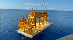
The project scope called for the installation of two 27,000-ft, 6-in. in 10-in. PIP flowlines, installation of two single-line dual-hub subsea pipeline end terminations (PLETs) at the Manatee well end, and two single-line dual-hub subsea PLETs at the Angus manifold end. All PLETs were to be installed into pre-determined target boxes.
Onshore activities were conducted at Global's deepwater facility in Carlyss, Louisiana, which includes a pipe assembly rack normally used to weld 40-ft joints of pipe into 2,790-ft stalks for spooling onto reel pipelay barges. For the Manatee project, the pipe stalks were reduced to 2,500 ft.
Prior to installation, Shell required fatigue analysis and static and dynamic analysis of the suspended pipe span for a range of environmental conditions, including a typical winter storm and loop currents. Specific concerns were current forces, vessel motions, and detailed end conditions at the upper end of the suspended pipe span with the effect of those environmental conditions on rollers, clamps, and equipment.
Engineering was required to develop and test a pipespan parameters monitoring system. Engineers developed graphs and procedures for pipelay vessel operators and field engineers to allow them to determine if measured pipelay parameters were within allowable ranges or if corrective actions were required. Considerations included change in vessel position or change in tension or ramp angle. Also required were circle graphs depicting maximum allowable vessel excursions under different operating conditions so that bending strains were not exceeded and the pipelines were installed within the specified right-of-way.
Following the fabrication of the calibration block used for automatic ultrasonic testing (AUT), development, and acceptance of the welding procedures and spoolability tests of the 6-in. and 10-in. pipelines and bulkheads, the actual welding began in February.
Specialized construction
Mechanized welding technology saves prod-uction time and produces higher-integrity welds than the conventional process. The technology uses pre-programmed welding parameters to guide the mechanized gas metal arc welding systems. AUT was used for weld inspection.
The 10-in. pipe was coated with 16 mm of FBE coating. The 6-in. pipe was coated with approximately 1.1 in. of low-density polyurethane insulating foam. The 4-lb foam was applied to the 6-in. pipe in 40-ft sections rather than the routine 3-ft half-shell foam insulation process, providing higher insulating reliability essential in Manatee's deepwater environment.
As the 40-ft sections of insulated 6-in. pipe were welded, split sleeves of the same type insulation were applied to the pipeline, creating a continuous flow of insulation. Spooled installation of continuous bonded insulation in PIP is an industry first. Bulkheads were later positioned every 2,500 ft.
The sheer weight of PIP construction necessitates special handling. A larger surface area must be provided to cradle the pipe in place in welding areas, on the pipe rack, and in pipelay areas.
The spooling of the PIP pipeline took place at the Carlyss facility working around the clock. Manatee Pipeline No. 1 and Manatee No. 2 were spooled continuously onto the Hercules prior to its departure for Green Canyon.
Pipelay initiated at the Angus manifold for each of the two pipelines and terminated at the Manatee wells. Anodes were installed every 625 ft as the pipe was laid on the seabed. Once the pipelay was complete, the Hercules picked up each pipeline end. A PLET was welded to the pipeline end, then lowered to the seabed in its target location. Four PLETs were installed, two at the Angus end and two at Manatee.
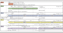
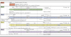
In advance, an outside bulkhead ring is welded to a pup piece of 10 in. (weld 2). On the pipe rack, the first 10-in. stalk is pulled onto the first 6-in. stalk, and the inner bulkhead ring welded to the 6-in. pipe (weld 1). The 10-in. pup piece with the outside bulkhead ring attached is then measured, cut, and welded to the 10-in. pipe on the rack (welds 3 & 4). The first 6-in. stalk is welded to the second 6-in. stalk (weld 5), and the second 10-in. stalk is pulled into place and welded (weld 6). The joint is then coated. The process is repeated 22 times.
