PART I: This is Part I of a two-part series. Part I focuses on wellhead and downhole space limitations for HP/HT wells. Part II, which will appear in a subsequent issue, will feature selected areas of concern.
Design and operational practices of high pressure/high temperature (HP/HT) oilfield equipment are well known in onshore and offshore platform environ-ments. HP/HT designs have to deal with the high energy situation associated with well control with respect to:
- Extreme component stress in hardware
- Dealing with very high density well control fluids
- Amplification of partial pressure of corrosive constituents (hydrogen sulfide and carbon dioxide)
- Material degradation at elevated temperatures.
Although substantial experience exists separately for HP/HT and deepwater subsea projects, "subsea HPHT" is challenged by the existence of both technical issues combined together, creating a new set of often contradictory problems. Subsea flowlines, pipelines and manifold gathering systems are often rated at much lower operating pressures than the tree to save on size weight (and cost). They are also exposed to cold seawater conditions.
Operating at lower pressures may require extraordinary choking requirements including: dual stage pressure drop configurations, use of special materials, and piping geometry requirements to deal with Thompson-Joule and erosion turbulence. In addition, thermal expansion during start-up and prolonged shut-in may require special piping geometry, connection strength, and annular access for well casing, well tubing, and delivery piping.
The makeup of HP/HT wellbore fluids also poses special challenges. The high pressure and temperature environment at the reservoir is very different from the lower seafloor temperature and infrastructure pressure. Cloud (wax), hydrate, and asphaltene appearance temperatures tend to be much higher than the infrastructure environment, requiring several difficult and complicated mitigation strategies, such as high temperature insulation and multi-bore chemical treatments, to be incorporated in downhole, subsea, and infrastructure designs.
The extremes of high energy associated with HP/HT equipment places increased demands on control systems as well. Hydraulic and electrical power needs to be greater for HP/HT applications to deal with the increased mechanical loads imposed by well control equipment (valves and chokes). Measurement and monitoring sensors need to be robust enough to reliably work at elevated HP/HT conditions. Furthermore, overall control system response times must be reduced to head off volatile transient effects found in drilling kick detection, production well control, and workover remediation.
Several definitions exist for HP/HT for drilling and production technology. Here, HP/HT is defined as the equipment and practices associated with a well's flow control and containment that requires "kill" pressures at the wellhead in excess of 10,000 psi, and/or a flowing wellhead temperature in excess of 250°F.
Currently, HP/HT equipment is often rated for both 15,000 psi and 350 degrees F service. These two factors, pressure and temperature, may not always go together, but manufacturers are developing a family of hardware that meets the widest range of HP/HT criteria, in an effort to hold down development costs and an explosion of option permutations.
Subsea HP/HT need
The evolution of the subsea technology has been steadily fueled by the progression of circumstances in three areas: increased wellbore size, higher pressure rating, and deeper water depths. These factors have continuously pushed the development and refinement of field architecture and hardware configurations as the oil and gas industry marches further offshore in search of deeper reservoirs, using as little infrastructure as possible to exploit prospects.
Manufacturers build three pressure classes of subsea hardware: 5000 psi, 10,000 psi, and recently 15,000 psi working pressure systems (again to minimize the number of wellbore size and pressure rating hardware permutations). The advent of 15,000 psi has also ushered in the preference for higher temperature service - above traditional 35-250°F service.
Interestingly, some have pushed the limits of "lesser" operating equipment to qualify for slightly "greater" service conditions by making use of the intrinsic hydrostatic pressure and low ambient temperature surrounding subsea equipment at great depths, along with the use of novel material and/or hardfacing techniques. The hydrostatic pressure creates a constant pressure vessel containment field, allowing for thinner wall sections and/or less material strength to be used for higher internal pressure service.
Strategic placement of non-metallic seals and components near the exterior of subsea hardware can take advantage of the heat sink effects of the seawater outside, keeping these components well within their maximum operating temperatures, regardless of the wellbore fluid temperature. Finally, the use of premium hardfacing at highly stressed locations (such as a gate valve's gate-to-seat interface) can mitigate galling or contact stress failure of materials at higher differential pressures using equipment geometries normally rated for lower differential pressure service. For example, special hardface treated 5,000 psi equipment may be used for up to 6,500 psi service, and 10,000 equipment up to 12,500 psi.
Design calculations, allowable safety factors, and factory acceptance tests (FAT) acceptance criteria must be scrutinized and agreed to between the manufacturer and end user to make sure that modifications are fit-for-purpose at "higher" service conditions. These adjustments are well within ISO and API specifications and design practice so long as the operating parameters and environment are clearly stated and documented. However, these allowances must be made compensated by lower testing pressures during FAT because of the absence of external hydrostatic pressure and low ambient temperature.
HP/HT technical challenges
However, these modification techniques only address HP/HT requirements 25-30 % above the working pressure of standard subsea equipment ratings. Greater HP/HT reservoir and well control requirements outstrip these limits, requiring a shift in how subsea equipment is designed and operated. Fundamental changes in material usage, new hardware geometries, faster equipment performance, more stringent installation and operating practices, or all of the above, are needed.
By definition, higher pressure and temperature basically equates to more trapped energy in wellbore fluids being contained and controlled. More stringent safety and limiting personnel accessibility to hardware through all phases of manufacture, installation and operation will be needed.
HP/HT well control equipment typically requires more energy from control systems to overcome the increased operating loads inside valves and connectors. Higher hydraulic operating pressures, on the order of 5,000 psi for tree and manifold hardware, and up to 17,500 psi for some downhole hardware, will become common to keep actuation devices within a reasonable envelope. Electrical sensors and operating hardware may have to switch to fiber-optics in order to survive the increased operating temperatures.
Materials used in pressure containing and pressure controlling hardware tend to "relax" at elevated operating temperatures. In turn, safety factors for HP/HT equipment will unavoidably have to be smaller than those enjoyed for lower pressure equipment. In general, higher alloy materials will be required, bringing with them additional challenges with respect to manufacturing process control, QA/QC, cost, and others.
Welding processes and heat treatment become more intrinsically a part of the material's performance, making sure that mechanical strength properties are uniform throughout. Detection of smaller sized defects in raw materials and welds are needed to make sure fracture mechanics of materials are not compromised.
Since uncontrolled flow from HP/HT sources to lower pressure infrastructure could cause catastrophic damage or loss of large volumes of wellbore fluids to the environment in a very short period of time, control system response times need to be reduced to meet requirements. Emergency shutdown close times on the order of 30 seconds and tighter detection thresholds of pressure and flow rates (erosional limits). Since tighter limit ranges often means more frequent 'tripping' of shutdown modes, smarter control logic will be required to monitor production transients and determine true out of bound conditions.
Hydogen sulfide, carbon dioxide
A common problem facing end users is the wise choice of materials given a limited understanding of corrosive elements in wellbore fluids. One of the most notable problems is quantifying the amount hydrogen sulfide, carbon dioxide, and other corrosive agents to define equipment service, choose materials and make knowledgeable estimates on corrosion allowances.
One of the most common misconceptions is determining material class. API and ISO base material class on partial pressure of hydrogen sulfide and carbon dioxide, not on weight or mol %. Gone are the days where the phrase "less than 1 mol percent" is sufficient in describing the amount of these corrosive agents. In this instance, a metallurgist must assume a 1 mol % value, which translates into a partial pressure of 100 psi pp (partial pressure) for a 10,000 psi working pressure, or 150 psi pp for 15,000 psi service. These values are order of magnitudes higher than limits set which require high corrosion resistant alloy (CRA) material usage (1.5 psi pp for hydrogen sulfide and 30 psi pp for carbon dioxide).
Failure to quantify these corrosive agents in terms of partial pressure instead of volume percentages may translate into unexpectedly high material costs for the end user (on the order of eight times higher for CRA than more traditional materials). Knowing where partial pressure is high may help influence the use of special field architecture or chemical treatments deal with corrosion or material failure.
'Hourglass' paradigm
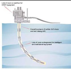
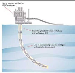
The hourglass paradigm is a phrase used to describe the situation subsea designers find themselves - wrestling between drilling interests wanting ever smaller wellheads, versus reservoir and production interests wanting fewer wells with ever larger production tubing.
Equipment sitting on the seafloor can be as large as is practically packaged, and downhole technology continues to advance in the areas of multilateral wellbores, downhole control, and separation. Unfortunately, both must meet or pass through the bore of the high pressure wellhead housing - the 'hourglass' bottleneck.
The tug of war between smaller casing sizes versus larger production bores is further magnified by HP/HT conditions. Drillers want smaller casing to deal with internal pressure and ever longer lengths as wells are drilled deeper, while reservoir analysts want large production tubing strings to maximize reservoir hydraulics. Unfortunately, both sides can forget the limits imposed by hoop stress when evaluating pipe programs:
s = PD/2t
The pipe outside diameter (D) and the well pressure (P) govern the type of pipe. The stress (s) and pipe wall thickness (t) are governed by the material selected and the required strength needed for the job and wellbore fluid conditions.
Many times, standard grade carbon steel is used in well casing construction, forcing wall thickness to grow to meet load and pressure requirements. A large wall thickness reduces the amount of available area for production tubing. This problem is exacerbated by HP/HT conditions, where allowable stress may have to be reduced for elevated temperature, deep wells require much longer pipe lengths (hence high weight loads), and HP/HT conditions exert high longitudinal and hoop loads on the pipe itself.
Tubing suspension equipment must be able to support the weight and pressure end loads developed by production tubing and yet provide adequate conduits for the production bore, annulus pressure access, and any downhole chemical, electrical, and hydraulic control lines. As downhole completion designs become more sophisticated and HP/HT wellbore fluids require multiple downhole chemical treatments, the number of extra control lines may grow upwards toward 8-10 lines.
This space dilemma becomes the major challenge for subsea designs in the future. Hence the paradigm will continue to exist until a new well design geometry or change in material usage is found to alleviate the lack of space or accept smaller production bores.
Thermal growth
The cycling between cold starts and prolonged high temperature operation of HP/HT wells also affect flowline/pipeline thermal growth, and well casing growth. Pipe growth from thermal expansion is a well understood phenomenon but extremely challenging to mitigate expansion in the subsea environment. Soils are typically soft, which promotes settling or partial burial of the pipeline, effectively anchoring the pipeline and restricting its movement.
Placing expansion loops, coils, curves, or other geometries in the pipe are (by their nature designed to be) structurally weak to minimize pipe stresses during growth. However, their weakness makes pipeline installation difficult since pipe strength is counted on when suspending the pipe from the pipelay vessel to the seafloor during installation.
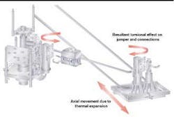
Many pipeline end terminations (PLET) are equipped with sliding structures to allow expansion and minimize end buckling. However, the jumper connections between PLETs and other subsea hardware must be designed to flex or bend as the relative distance between subsea hardware and the PLET changes. This relative movement also induces torsional and bending moment loads on the jumper's end connections.
Well casing growth is also well understood. Current observations note that wells may grow from 2.5 in. to 6 in. over extended periods from several months to several years. Inside the well, casing strings can be "locked down" using special latching hardware that mechanically restrains casing growth relative to the high pressure housing.
However, external growth of the well may pose space-out and residual stress loads in templates where wells are an integral part of a subsea structure and its connected piping. Clustered well arrangements (where wells are separated from manifolds and gathering structures by a flowline jumper) are less sensitive to end growth.
Performance issues
Technology designs and material usages exist for HP/HT service, just not as prevalent in subsea designs. Valve and sealing technology for surface applications has a well established record, understanding gap growth between seals, creep and downgrading material strength at elevated temperatures, and thermal induced mechanical stresses between components. Finite element analysis tools and sophisticated testing and high performance materials currently found have been used to identify high stress locations and mitigate their effects accordingly.
Another obvious design trend is to minimize the seal diameter of components to minimize mechanical end load effects as HP/HT requirements grow. However, this becomes another aspect of the 'hourglass' paradigm that must be guarded against. Selecting CRA materials provide for HP/HT applications provides the needed high mechanical strength (in addition to corrosion resistance) for current hardware geometries, but at the expense of more costly raw material and more difficult machining and fabrication. Smaller seal diameters and locking locations allows for more conventional material usage, but at the expense of production throughput sizes.
Less obvious are the detrimental effects of HP/HT on friction and lubrication. Friction also increases dramatically between hardfaced surfaces as temperatures increases above 250
Design codes and industry standards and practices are lagging behind, making it more difficult to design or verify that hardware is fit-for-purpose. In addition, many classic calculation techniques have used thin wall pressure vessel assumptions that may have to give way to thick walled calculation assumptions for HP/HT applications. Therefore, future hardware development and refinement may be slowed by novel qualification programs and sophisticated design practices until the subsea HP/HT market gains maturity.
Reference
Contact authors at FMC Kongsberg Subsea for a full list of references.
Acknowledgment
The staff and management of FMC Kongsberg Subsea provided critical review and support in developing this paper.
