Håkon Skofgteland - Aker Solutions
Subsea gas compression is cost effective for gas fields requiring pressure boosting. Typical applications are gas fields with long tiebacks to shore or to host platforms. The main equipment includes the separator, compressor, pump, and cooler. The subsea compression system currently is being built as part of the Ormen Lange pilot project. This is the world’s first subsea compression project. The Ormen Lange pilot is a full-scale, 12.5 MW compression train which equals one of the four trains planned for the future Ormen Lange subsea compression station.
Aker Solutions has two main solutions for the subsea compression system:
- 1. Compact GasBooster: Small-medium units up to 6 MW
- 2. GasBooster: Large capacity units up to 15 MW
The Compact GasBooster is one autonomous module including all required process and control equipment.
The GasBooster for large capacity units is a modularized system with separately retrievable separator, compressor, and pump modules.
The Ormen Lange gas field 120 km (75 mi) off the west coast of Norway is expected to need pressure boosting around or after 2015 to maintain plateau production and to increase recovery. Four 12.5 MW subsea compressor trains will be required to handle 60 MMcm/d (2.1 bcf/d) of gas and 7,200 cm/d (254,266 cf/d) of condensate. The subsea compression system will lead to significant cost savings compared to the alternative gas compression platform.
Subsea compression is also thought to be the best solution for the Åsgard field to maintain a minimum flow to avoid slug formation. Åsgard is off the west coast of Norway and tieback distance from the subsea compression to the platform is 45 km (28 mi). Extensive equipment testing and a FEED are under way for the Åsgard Minimum Flow Project.
Benefits of subsea compression
The added value of subsea compression depends on several factors such as the type of reservoir, tieback distance, water depth, and production system. Following are the main items that are usually considered:
Flow assurance:Gas fields often are developed with subsea wells and multiphase transport to onshore facilities or to offshore processing platforms. The flow assurance strategy usually gives restriction to the minimum flow rate to avoid severe slug production. A problem arises when the wellhead pressure declines over time and the pipeline export flowrate decreases to the critical value. Subsea gas compression can be installed to boost the gas-condensate and increase the flowrate in the export pipelines.
An alternative solution with subsea gas compression is to separate, boost, and transport the gas and liquid/condensate as separate phases in two export pipelines.
Recovery: Subsea compression can increase production and recovery from the reservoir by reducing back-pressure on the wells. Ormen Lange is an example of a gas-condensate field that will face declining reservoir pressure and decreased production rate.
Costs: Subsea gas compression is a cost beneficial alternative to topside compression platforms. Studies by StatoilHydro for the Ormen Lange gas compression show that a subsea compression station can reduce capital cost as much as 50% compared to a conventional platform with compression, and operating cost for a subsea compression station is reduced without a platform to man.
Safety: Installing a subsea compression station instead of a platform eliminates the need for offshore manning, helicopter transport, and offshore supply, and increases safety. Offshore operation is required only during installation or retrieval and replacement of subsea modules for maintenance and repair.
Emissions:There are no emissions or disposals from a subsea compression system. The only hazardous fluids in a subsea compression station is MEG used for hydrate inhibition and the hydrocarbon gas-condensate production itself.
Calculations by Aker Solutions indicate CO2 emissions could be reduced 60% in the construction of the subsea station compared with building a floating platform.
Environment: Subsea means there are no surface facilities exposed to harsh weather or ice, which is critical in arctic regions.
GasBooster
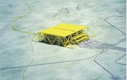
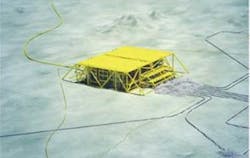
The arrangement of the GasBooster system including one 12.5 MW compression train has the following dimensions:
- Footprint: 21 m x 17 m (69 ft x 56 ft)
- Height: 13.5 m (44 ft)
- Total Weight: 1,100 metric tons (1,213 tons).
The GasBooster system can be arranged with up to four parallel compressor trains on one subsea template. The total compression power can be up to 60 MW. Each of the compressor trains comprises the following main retrievable process and power modules:
- Separator/slug catcher module
- Compressor module: GasBooster
- Pump or liquid boosting module: LiquidBooster
- Variable speed drive module for the compressor and the pump
- Circuit breaker modules for power supply to each compressor train
- Uninterruptible power supply and utility power distribution module.
The arrangement of the station is made to satisfy the process conditions and to minimize and simplify the interfaces between modules, especially for the power modules to reduce both cable lengths and high voltage electrical wet-mate connections where possible.
The process modules are designed to avoid pockets/dead legs in the piping system and prevent build-up and clogging of solids in the liquid piping and to ensure that any liquid condensation in the gas lines is sloped back to the separator vessel. The pump module is elevated below the separator module to satisfy the net positive suction head (NPSH) requirement. Subsea mechanical connections and ROV operated isolation valves are included to allow separate process module retrieval. The mechanical clamp connectors used are a variation of both single- and multi-bore types depending on the function and size of the connecting piping. Each clamp connector has an interface for ROV-carried torque tools.
Critical control and instrument equipment is placed in retrievable process modules or onto separate removable control modules. In general, ROV access to all subsea valve operation is possible without the need for opening the protection hatch.
Process system
The GasBooster system is directly exposed to the wellstream so the process equipment must handle varying composition of unprocessed hydrocarbon gas and liquid, produced water, sand, and chemicals injected at the wellheads. The process system must be flexible as the gas-liquid ratio that will vary over the production period due to changes in reservoir pressure, possible water breakthrough, and tie-in of new wells.
The system also will be exposed to liquid slugs with various hold-ups and frequencies due to well start-up, pressure transients, and terrain induced slugging.
Interventions of subsea systems are costly. System design must focus on robustness and reliability. The main design principle is to include an inlet separator or slug catcher to protect the compressor against liquid and sand/fines that lead to excessive wearing and reduced availability. The separator will work as a slug catcher and have the required volume to accumulate the slugs being produced.
The liquid and sand/fines removed in the separator are boosted by either a centrifugal pump unit or by gas pressure drainage. Which one depends on liquid flowrate and required head.
The centrifugal pump has high flow capacity, but the pump needs a net positive suction head of 4 m (13 ft) or more. This impacts the total height of the subsea compression station.
The gas pressure drainage is a patented solution that uses the energy of the compressed gas to boost the liquid. The solution does not include any rotating units or need for electrical power supply, and the reliability and robustness is high.
Compressor unit
The GasBooster subsea compressor developed by Aker Solutions is a patented design. The centrifugal compressor and high speed motor are installed in a common pressure vessel. The unit has magnetic bearings so parts with low reliability like gear and conventional bearings are avoided. The only utility supply required is the low voltage power to the magnetic bearings.
The GasBooster can be used for centrifugal compressors, high speed motors, and magnetic bearings from most vendors.
The motor-compressor unit can be either horizontal or vertical in orientation. The vertical configuration gives a smaller footprint which benefits subsea station arrangement as well as subsea installation and intervention of the compressor module. The electrical motor is above the compressor for optimum protection against any liquid or seawater leaks into the unit. In the vertical arrangement, any liquid droplets and solids particles settle by gravity and collect at the bottom of the compressor vessel.
The gas-filled motor operates in a closed volume with a barrier between the motor and the compressor. The motor cooling gas is circulated in the motor enclosure by an impeller mounted on the motor shaft and is cooled in an external seawater cooler. The closed motor cooling loop means that the motor is less exposed to the unprocessed gas being compressed in the compressor.
Separator unit
The subsea separator is a vertically orientated pressure vessel designed for accumulation of liquid, separation of gas/liquid, and demisting of gas. The liquid level is detected by instrumentation, and is controlled by a variable speed driven pump or a choke valve on the liquid recycle line.
The separator is designed to accommodate slugs expected from terrain induced and transient slugging. The separator will have sufficient volume between normal and high liquid level setting to absorb the liquid slug volume. The internals are designed to withstand forces generated by slugging for the lifetime of the separator.
Gas is demisted by devices with an open flow path sufficient to avoid clogging. Gas demisting performance is conservative relative the compressor vendor acceptance for liquid entrainment in the gas phase to the compressor.
Solids in the wellstream are separated in the separator together with the liquid. The separator must ensure that no solids are accumulated in the gas demisting device or in the bottom of the separator.
The subsea cooler cools the gas in the compressor recycle line and the motor circulation gas. Cooler performance may degrade over time due to biological growth and contaminates caused by mineral deposits. The cooler heat exchanging surface must be increased to take this into account.
The LiquidBooster pump is a vertically oriented multistage centrifugal pump with liquid-filled motor. The pump has a barrier fluid pressure control system capable of following rapid process pressure variation to avoid process fluid leaks into the pump motor. The system maintains an overpressure compared to the process pressure during all conceivable process system transient operations.
A LiquidBooster currently is being delivered to the Tyrihans project as well as to Ormen Lange.
Sand/fines/solids entering the compression station are separated in the separator and transported via the liquid pump to the discharge pipeline so the liquid pump must handle high sand concentrations.
High voltage power
High voltage power to the subsea compression station comes from shore or an offshore platform via subsea power cables. The power distribution and variable speed drive (VSD) system must run the high speed compressor motor at required speed and torque with high level of reliability and availability.
The need for subsea VSD depends on the tieback distance and also the duty and frequency. In general, when running a subsea motor at variable speed/frequency, a long power cable represents a challenge with regard to power system stability, resonances, harmonics, power losses/voltage drop, torque pulsations, and control algorithms.
The high speed motors for compressors typically have maximum operating speeds from 6,000 to 12,000 rpm (100 to 200 Hz). Electrical power simulations show that with distances up to approximately 50 km (31 mi), the electrical drives can be located topside. To control the speed of each subsea motor independently, separate power cables are installed from each topside VSD to the dedicated subsea motor.
The subsea VSD converter and the circuit breaker are inside pressure vessels designed for the external seawater pressure and with atmospheric pressure internally. The VSD converter power electronics operate in a nitrogen atmosphere and with a closed internal cooling loop and an external heat exchanger.
The subsea transformers are in oil-filled and pressure-compensated units.
Controls
To operate the subsea compressor system, an all-electric control system is being qualified by Aker Solutions as part of the Ormen Lange subsea compression pilot project. The onshore or platform equipment will connect to the subsea equipment via fiber-optic cables included in the electrical cable supplying high voltage power.
The all-electric control system qualified by Aker Solutions consists of:
- Dual optical fiber in the main power cable/umbilical. 100 MB/s networks up to 120 km (75 mi)
- Topside subsea control unit with optical modems for subsea communications
- Fully redundant subsea uninterruptible power supply with a low power sleep mode for minimal battery drain
- Subsea control module for each subsea compressor train, each housing dual subsea electronic modules. This is the hub for communications between the surface and the subsea units
- Subsea local area network (LAN)
- Subsea process shutdown system with SIL2 rating
- Subsea process control loops
- Real-time condition monitoring.
The subsea uninterruptible power unit provides auxiliary power to the pilot system in case of power loss on the main high voltage (HV) power supply circuit. Should shore power fail, the UPS system can be commanded to power off individual subsea units. Individual units may be powered on to make available status or diagnostic information.
The Ormen Lange subsea compression station pilot is scheduled for delivery and installation in 2010 in the test pit at Nyhamna, the Ormen Lange onshore facilities. The compressor train has a capacity of 15-20 MSm3/sd and a compressor shaft power of 12.5 MW.
The compressor train comprises the following main retrievable process and power modules:
- Process system:
- –Separator module from Aker Solutions. Size: ID: 2.8 m; T/T: 6.7 m.
- –GasBooster subsea compressor module from Aker Solutions, including motor-compressor from GE Oil & Gas. Duty: 12.5 MW and speed up to 12,500 rpm.
- –LiquidBooster subsea pump module from Aker Solutions. Design duty: 400 kW.
- –Anti-surge cooler module from Aker Solutions. Design duty: 9 MW.
- HV electrical power system:
- –Variable speed drive for the compressor from ConverTeam.
- –Variable speed drive for the pump from ConverTeam.
- –Circuit breakers from ConverTeam for power supply to each pair of compressor trains.
- HV electrical connections with penetrator, jumper, and wet-mate:
- –22 kV 900A Deutsch.
- –6,6 kV 1600A Deutsch.
- –2,5 kV 150A Tronic.
- Control system:
- –All-electrical control system from Aker Solutions.
- –100 Mb/s TCP/IP fiber-optic link to the shore.
- –Topside subsea control unit with optical modems for subsea communications.
- –Fully redundant subsea uninterruptible power supply with a low power sleep mode, with minimal battery drain. UPS duty: 2 x 50 kW.
Subsea control module housing dual SEMs.
The Nyhamna test pit has a cooling water system with continuous seawater flow into and out of the test pit to cool equipment during operation. The pilot will be operated with the real wellstream composition from Ormen Lange, and the test facilities are equipped to emulate slug production, sand production, and other operating conditions for the future Ormen Lange subsea compression station.
