Cathal Kelly, David Brookes - BP
Gunder Homstvedt, Truls Normann, Klas Göran Eriksson, Hallgeir Melbø - Aker Solutions
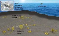
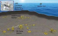
The King field complex currently consists of the King (D5 and D6) wells and the King West (D3) well. All three are owned by BP and produce back to theMarlin TLP, also operated by BP. The TLP is 86 mi (138 km) south-southeast of Venice, Louisiana, in the Gulf of Mexico’s Viosca Knoll block 915 in a water depth of 3,245 ft (989 m). Several fields tieback to the TLP and one of the longest is the King Field Complex. The wells are connected via rigid jumpers to one of the two flowlines going back to the Marlin TLP approximately 28 km (17 mi) away.
As reservoir pressure declines, BP studied ways to keep up production and to increase the field life. Subsea boosting came out favorably in these evaluations. BP invited tenders for a suitable pump system and Aker Solutions won with a pump system based on the MultiBooster. The pump system was delivered in the summer of 2007 and fully commissioned in November 2007.
Several subsea pump layouts were evaluated to get the best possible production gain. The conclusion was that one pump station should be close to the D3 and D5 wells and the second pump should handle flow from D6. A small manifold at the D5 pump station would commingle the flow from D3 and D5 and route it to the pump.
To simplify connecting the pumps to the wells and flowlines and to reduce shut-in time during installation, a MARS choke insert system was used. The original tree choke insert was replaced with a dual bore choke insert assembly and universal work platform (UWP) landed on top of the christmas tree. This allows well flow to divert through the pumps and back into the flowline without new connection points. Since the wells and the flowline can be isolated by already installed valves, there was no need to de-pressurize and clean the pipeline at hook-up, resulting in risk reduction and time and cost savings.
D5/D3 and D6 well flows can be commingled via both pipelines or individually, with the existing pigging valves.
The pump system consists of the following sub-systems:
- –Structure and manifold with by-pass and isolation valves
- –Pump module with instrumentation and barrier fluid/lube oil system
- –Topside master control station with power supply and modems
- –Topside hydraulic power unit (HPU)
- –Subsea control module with necessary jumpers
- –Topside power container with two variable speed drives (VSD)
- –Subsea power jumpers
- –D3/D5 umbilical termination assembly (UTA)
- –In-field umbilical D6 UTA.
The pump station was installed as a complete unit. The pump module, barrier fluid controller, and the control module are retrievable individually.
Pump module
The pump module at BP King project is based on a twin-screw principle. The pump core is by Joh. Heinr. Bornemann GmbH and integrated into a pressure casing by Aker Solutions. The pump core is the same design as used in a number of topside applications. The key challenges in applying this type of pump to a deepwater application were:
- Qualifying a pump/motor casing to handle the water depth and shut-in pressure
- Establishing a barrier fluid/lube oil system pressure control system for such water depths
- Tie-in arrangement of the flowline, power, and instrumentation connections.
A twin-screw pump for multiphase boosting has double ended, inter-meshing screws with external timing gears and bearings.
Twin-screw pump principle (Courtesy of Bornemann).
The gas/liquid mixture is fed to the center of the screws. As the screws rotate, chambers are formed between the individual screw flights. These chambers hold a given volume of fluid, moving it axially as the screws rotate from the center to the ends of the screws. This provides axial balancing of the rotating elements. The screws are centered inside a liner by bearing support and synchronized by a timing gear so all metal-to-metal contact is avoided. The fluid collected in the small gaps formed between the screws and the liner act as a seal. The pump liner has a chrome-oxide layer and the screws have tungsten carbide in order to withstand wear by particles.
Essential pump system features:
- It keeps an almost constant volumetric pumping ratio independent of gas volume fraction (GVF), i.e. from 0 to 100% GVF
- No need to mix liquid and gas in a homogenizer upstream of the pump suction, i.e. compact system
- The flow rate is nearly proportional to the speed of the pump, i.e. easy to control for obtaining the desired flow rate
- The pump always meets the outlet back-pressure whether pumping liquid and/or gas, i.e. independent of fluid density
- The twin-screw pump is self-priming and can operate with 100% gas for a period up to 0.5 hour and continuously with gas fractions up 98%.
- The pump can handle highly viscous fluid and has low tendency to create emulsions due to low speed and low shear forces on the fluid.
The pump and motor casings had to be designed and tested for an internal design pressure of 5,000 psi (345 bar) and an external design pressure 2,500 psi (172 bar) for 1,700 m (5,577 ft) water depth.
Substantial work went into material selection and casing design. One major task was to qualify the main seal in the interconnection between the two casings. The pump core and the motor core were inserted as cartridges into the casings.
Barrier fluid/lube oil system
A barrier fluid between the pump cavity and the motor/bearing cavity is essential to keep contaminants out of the bearings and motor internals. The bearings and seals need lubrication, and to keep it simple, finding a single fluid to handle both functions was vital.
The pump core requires good lubrication to its highly loaded bearings and timing gear. The motor core requires a cooling fluid with good dielectric properties. While the pump required a lubricant with high viscosity to secure good lubrication, high viscosity would lead to high losses in the motor. High viscosity also is a problem when supplied through a small, long pipe in the umbilical. A compromise was found in selecting a mineral oil with moderate viscosity as the lubrication, cooling, and barrier fluid.
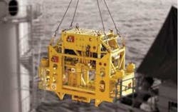
Pump station during installation (Courtesy of BP).
The barrier fluid/lube oil is fed through a line in the umbilical to an accumulator bank by dedicated topside hydraulic power unit (HPU). This HPU has filtration and water removal equipment. At the pump module, a dual redundant set of retrievable pressure controllers ensure that the barrier fluid/lube oil always has a pressure about 15 bar (218 psi) higher than the highest pressure in the pump cavity. The fluid pumps through an external cooler to remove heat generated by the motor.
Pump module arrangement
To make the most critical units retrievable, the following arrangement is included:
- The pump module is fully self-contained with following flowline connection arrangement:
- –Suction and discharge line connection by vertical oriented clamp connectors at the bottom
- –Soft landing cylinders arranged with a lift capability in order to replace connector seal without removing the pump station
- –ROV-operated tools for connector seal replacement and testing
- ROV installed jumpers for instrumentation, hydraulics, and HV power
- ROV installed canisters for barrier fluid regulators. Dual, redundant arrangement that allow automatic switching from one to the other
- Retrievable subsea control module.
High-voltage power supply
The BP King subsea high voltage (HV) power system is a double world record on step-out distance between a VSD and a motor, with a total distance of 28 km (17 mi) down to the far end D6 Pump (24 km [15 mi] for D5 pump). This exceeds the perceived limit for such systems without high voltage transmission and without subsea transformers, which makes it possible to increase simplicity, reliability, reduce investment cost, and to reach wells/assets that were not within reach in the past.
The HV system consists of the following main items:
- Two 1,100 kW/6.6 kV/60 Hz Aker Solutions subsea multiphase pump modules
- Two Siemens Perfect Harmony Variable Speed Drives (VSD, each consisting of step-down transformer, 48-pulse frequency converter, and sine wave filter) with the possibility to run up to 9 kV on the drive output without step-up transformer. The drive consists of 24 power cells (eight per phase) with a patented automatic by-pass function, which means that up to three cells can be lost without shut-down. A cell can be replaced with a spare in less than 30 minutes
- Both VSDs and pump control systems were delivered in a container (Powell Industries Inc.) for easier and faster installation and commissioning. The unit includes A60 fire rating for Ex Zone, Fire & Gas system, pressurization system, five HVAC air conditioning units with N+1 redundancy, FM200 fire suppression system, etc.
- One Nexans main power umbilical (2 x 3 x 1 x 95 sq mm 12/20(24) kV) going to pump/well D5 with power lines for both pumps
- One additional 4-km (2.5-mi) Nexans infield power umbilical for further distribution to the far end pump/well D6
- HV connection system based on Tronic 6/10(12) kV 300A, single phase connectors/jumpers/penetrators, qualified for 3,000 m (9,842 ft)
- Subsea 200 ft (61 m) long Oceaneering HV flying leads with Tronic HV connectors between UTAs for distribution to pump modules
- The VSD output features quick-connect elbows that make it possible to disconnect and ground the output cables safely on one VSD to do maintenance without having to shut down the other pump.
Selected pump shaft power and system components/ratings/available boost were also decided by the fact that the platform had a limited generator power reserve of max 1.3 MW per pump system.
Aker Solutions is applying this experience to the Tyrihans subsea raw seawater injection project, where two 2.7 MW subsea pumps (world’s largest) are supplied through a 31-km (19-mi) power cable (start-up 2009) and the current Ormen Lange Subsea Compression Pilot project, where Aker Solutions is designing a 125-km (78-mi) long step-out system with 70 MVA transmission and four subsea 12.5 MW compressors and subsea VSDs, including circuit breakers and uninterruptible power supply units.
Control and monitoring system
The control system has fairly few subsea control functions (16 sensors and five hydraulic functions), and is simpler than a standard christmas tree control system. The challenges were related to the interference from the HV power lines in the 28 km umbilical, which are shared by all services.
For this reason, data communication between topside and subsea is via dual redundant fiber-optic lines, operating at 10 Mbit/s speed. Fiber-optic communication is inherently impervious to disturbance from the HV lines.
The LV power system (which powers the subsea control system) is influenced by the HV system, especially if a ground-fault occurs. As for the HV system, the LV electrical systems also are designed to operate with continuous ground-fault.
The umbilical ends in a UTA. It has a subsea wet-mateable HV connector, connectors for LV power and fiber-optics, and connections for fluids (hydraulic fluid, methanol, and lube oil). There are spare lines in the umbilical, so most faults in the umbilical can be mitigated simply by reconnection of subsea jumpers.
Data monitoring
Pump system data are collected and sent to shore for analysis by the Aker Solutions OPDM (Online Pump Data Monitoring) system. The pump system’s performance is evaluated once a week to capture any change. The pump system is expected to operate at least five years at nominal speed and power, but sooner or later will need to be retrieved for service. When a pump is retrieved it typically is replaced by a spare pump. Being able to predict when this needs to be done has a great cost benefit, as an unplanned intervention can cause a production loss of up to a month, while a planned intervention can be done in 24 hours.
The system maps performance indicators which can be used to predict when the pump performance will decrease below acceptable levels. The intention is to provide advance warning so a planned intervention can be made. The three performance indicators currently monitored weekly are lube oil consumption, number of active subsea lube oil accumulators, and pump efficiency.
When running the OPDM system, data is fed into a set of analysis routines which produce a status indication.
Commissioning and operation
The pumps have been at their final subsea location for more than a year, and they have been in successful operation. Installation was complex. By splitting the installation activities into phases and using various vessels, the operation was executed flexibly and efficiently within a high-demand installation contractor market.
Careful planning and involving key people in extensive training, stack-up tests, and pre-deployment work helped make this complex operation a success. All sub-systems were checked during commissioning including extensive pressure testing.
After successful start-up in November 2007, the system operation is summarized as follows:
- Both pumps are running stably and all sub-systems are working without limitations or problems
- The D3 well produces at higher pressure than initially anticipated in the reservoir analysis. The system is tuned to allow this well, under the current conditions, to produce directly to the flowline and by-pass the pump. The pump, therefore, is boosting only well D5
- Due to lower viscosity and higher gas content than anticipated, the pumps run at full speed without using the full installed power. When water break-through occurs, more of the available power margin will be used.
Acknowledgements
The BP King Project is a success due to efficient and productive cooperation between several parties. Foremost, excellent cooperation between the project teams of BP America and Aker Solutions made this project possible. Essential contributions were made within a very broad range of technical disciplines by both parties. Furthermore, the managements in both companies are acknowledged for their dedicated support throughout the project.
Record breaking design and technology achievements were made possible by a close and enthusiastic cooperation between the project team and a number of sub-suppliers, among those: Bornemann, Loher, Siemens, Ottestad, Oceaneering, and DES. This also includes close cooperation with Nexans and SINTEF Energy Research on the power umbilical design.
The BP King Pumping Project’s significant technical achievements include:
- First ever marinizing of a twin-screw multiphase boosting station for very deep waters
- A record long step-out (28 km or 17.5 mi) of high voltage power supply to two 1.3 MW pumping stations, designed to operate with a potential earth fault for increased robustness and availability
- Qualifying of a barrier fluid/lube oil system including pressure regulation for operation at 1,700 m (5,577 ft) water depth
- Qualifying motor/pump casing and seal technology for the pump unit
- Establishing a fiber-optic based pump control and monitoring system for the pump stations
- Establishing an Online Pump Data and Monitoring support function
- Successful installation and commissioning at world record water depths for such a system.
