Glynn Williams
Sensor Highway
Channeling of hydraulics with fiber optics
The use of optical sensors for downhole monitoring is being studied more closely now that the technology is showing
the capability of operating reliably in tough conditions. Probably the first commercial fiber optic pressure sensor was developed as a consequence of a joint industry program between Norske Shell and Alcatel Kabel Norge with BP Norway and Norsk Hydro as co-sponsors. This system was designed to offer permanent downhole pressure and temperature measurement and operate at the elevated temperatures encountered under HP/HT conditions. It was developed to address perceived shortcomings in reliability that conventional permanent gauge
s encounter at temperatures of 120-150°C.
The optical sensor element comprises a micro-machined silicon oscillator which is activated and read optically through a single fiber. The fiber's resonant frequency is determined by the pressure and temperature downhole. Its operating principle is practically insensitive to fluctuations in signal attenuation and allows for remote operation, with more than 25 km between the gauge and the acquisition unit. Over five of these systems have so far been installed.
Another method of deploying optical sensors uses a conduit concept developed by Sensor Highway of Andover, UK, which allows thin filament sensors to be placed in the well using fluid drag. The system offers the following advantages:
- Downhole splices in the optical fiber are eliminated
- Sensors can be installed at any time, even after the well has been completed
- Sensors can be replaced if faulty, or upgraded during the life of the well
- Sensors can also be "buffered" using specially formulated fluids that are placed in the conduit.
Since May 1998, Sensor Highway has been working with Baker Hughes to develop new fiber-optic based monitoring systems for drilling, completions and production. Interest is now increasing from offshore operators, with discussions under way for a variety of applications off northwest Europe and west Africa, including gas flow measurement, and chemical and water injection.
Wytch Farm
Results from early work in horizontal steam flood wells indicated that fiber optic-distributed temperature sensors installed in the well using the Sensor Highway conduit can be an alternative to running coiled tubing-conveyed production logs. It has since been demonstrated that the transfer of distributed temperature measurements from onshore shallow horizontal wells to more complex wells in Europe is possible.Two wells in BP's Wytch Farm onshore/offshore development on the southern English coast have been completed with fiber optic sensors to monitor downhole electrical submersible pumps and well performance. One of the wells is a relatively simple vertical completion with an ESP, while the other is a more complex horizontal dual-purpose well.
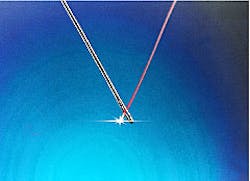
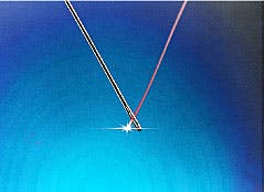
155 micron diameter optical fiber as deployed in the Sensor Highway temperature measurement system.The distributed temperature data from the simple ESP completion was effective in describing the operating condition of the ESP pump, while in the horizontal well's case, there are encouraging indications that inflow along the horizontal section is observed.
The dual purpose injector/producer well is equipped with a cross-flow sub that allows produced water to be re-injected below the oil/water boundary while crude is produced along a long horizontal section. Conventional PLTs cannot be run in this well because the ESP requires a shroud and there is no logging by-pass. Furthermore, the cross-flow sub is not full bore.
Perforation response
The well's measured depth is over 6,000 meters with an oil producing interval of about 1,000 meters. The main objective was to determine whether continuous distributed temperature measurements along the producing interval could be used to describe the production inflow response along the perforated section.Baker Hughes substantially provided the completion, an evolution from the earlier Wytch Farm M10 well completion design. Modification was necessary to allow the conduit to be placed along the producing interval. BP had also specified a one-trip completion without the need for coiled tubing operations. A hydraulic wet connect system was also developed by Baker Oil Tools to permit installation of the fiber optic sensors below the ESP.
Numerous packer options were examined to allow the conduit to pass along the horizontal section, yet still allow the completion to be run in a single trip. To this end a Baker JMZX packer was chosen as the linear tie back packer which proved ideal, as the large bore allowed the running of the dual 1/4-in. conduit beside the 1/2-in. flush joint tubing. The dual conduits were clamped to the 4 1/2-in. tubing running along the producing interval and ran to a turn-around sub that set above the lower packer - a Baker SABL-3 Hydro set design.
The completion was run exactly to plan, with two 1/4-in., steel conduits being successfully installed in the pre-perforated horizontal producing section. The wet-connect tool was operated during the completion phase to enable the completion space-out to be performed.
Prior to disconnect, fluid pressure in the 1/4-in, conduit was increased to allow the interlock function to be disabled and the tool was disconnected, parting the string below the shrouded ESP. Following space-out, the tool was re-connected and the conduit successfully pressure tested.
A completed loop of 1/4-in., conduit, 10,000 meters long, had been installed in a complex horizontal well without difficulty, including a 1,000-meter horizontal section where the conduit was clamped to the outside of 4 1/2-in. tubing inside a 7-in. liner. The next step was to install 10,000 meters length of optical fiber by means of fluid drag into the 1/4-in, conduit loop.
Initial attempts to do this met with failure, as the fiber "refused" to deploy into the conduit. Following re-evaluation, it was evident that the 1/4-in. conduit had become contaminated by hydraulic oil and required cleaning. Once flushed with isopropanol, the fiber went through without difficulty. Initially, a 6,000-meter-length fiber was installed to operate in single-ended mode. Following evaluation in service, this will later be replaced by a 10,000-meter loop of fiber.
Fiber-optic distributed temperature data is now being gathered in a well from which real-time well performance data would otherwise have been unattainable. Early results suggest the temperature profile along the 1,000-meter horizontal section is not linear and that there are regions of greater or lesser temperatures. Tests are now being planned whereby distributed temperature data will be collected while varying both injection and production rates.
Tool operation
Extending the use of fiber optics beyond pure monitoring of the well is logical if the concept of increased reliability is to be accepted for the sensors. Use of fiber optics to manage the whole intelligent well operation may sound far fetched, but fiber optics are used to provide power to equipment in other industries. Sensor Highway is working to transfer this technology downhole.Through controlling the channeling of hydraulics with fiber optic switches, it is possible to operate an array of tools located within the well bore from the surface. Numerous fiber optic actuators are available that are capable of exerting large forces, with sufficient displacements ranging from several micrometers to a few millimeters.
Piezoelectric actuators have been adopted widely. Their main advantages are generation of large forces, high movement resolution, high dynamics and the potential for miniaturization. We envisage it will be possible to operate certain hydraulic devices such as safety valves and sliding sleeves, to optimize gas lift valves and to set packers using these systems.
The relative simplicity of fiber optics minimizes the likelihood of failure, which maximizes the design's longevity. This development is ongoing - Baker Oil Tools/Sensor Highway expect to have a design ready for testing in late 1999. It will offer the following advantages:
- Designed for 4 1/2-in. tubing in 32 lb/ft 7-in. casing
- Composite sensing and power cable using fiber optics only with no interference from strong electro-magnetic fields
- Miniature, high power actuators that can be packaged easily into small annular spaces
- Integration with small remote fiber optic sensors to give closed loop sensing and control of downhole components
- Simple interfacing with proven hydraulic systems.
Reference
Individual Advancements Towards Developing Smart Reservoirs, organized by SMi in London, November 1998.Copyright 1999 Oil & Gas Journal. All Rights Reserved.


