Stéphane Taxy
Emilie Ratabouil
Guillaume Geoffroy
DORIS Engineering
For more than a decade, deepwater fields have been in productionoffshore West Africa. The typical field development consists of an FPSO with subsea production equipment and a network of flowlines, risers, and umbilicals. Once onstream, the operator's objective is to extend the production plateau, and therefore maximize the use of its facilities, by incorporating new reserves. Such development is often performed by extending the subsea network through the connection of additional wells, the extension of the existing flowline, the laying of new production lines and risers, or by installing subsea boosting stations. The development of new reservoirs may also require topsides modification. The congestion of existing topsides and subsea architecture often presents issues for the designer seeking to arrive at a design that provides sufficient operability.
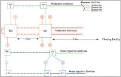
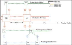
When the reserves of the new field are sufficiently large and there are available slots on the FPSO for future risers, the development of a marginal field could consist of an independent new subsea network directly tied back to the existing process facilities. When this is not the case, a subsea brownfield network may be an alternative to develop the new field while reducing the impact on the floating facilities. The objective is then to use existing subsea equipment as much as possible. The following presents the context of deepwater brownfield development when limited/no riser slots are available on the floating facilities and will review the different options available to the designer.
Production line extension
The production line is the most complex system of the subsea brownfield development with respect toflow assurance issues. The intent is to identify the root modifications induced by a subsea brownfield on the production systems: the length increase and the possible change of elevation, if the new field is deeper. Keeping the same diameter as the existing flowline is also a criterion.
The extension of an existing system to produce a new field means that the line will be longer and sometimes deeper. Such an increase will have an impact on the flowline inventory, the temperature profile, and the pressure profile. The wellhead flowing temperature from the new wells, located at the end of the production loop, should be warm enough to provide a temperature profile in line with the existing operating range. To avoid hydrate formation risk during production shutdown and restart, the typical preservation scheme is based on fluid displacement of the subsea lines arranged in a production loop or hybrid loop. Such a scheme will always be impacted adversely when the line is lengthened: the time to depressurize the line will be longer (for a given flare capacity at topsides) since the initial fluid inventory is greater (initial mass of gas and initial pressure) and the time to displace the line will be longer for a given displacement flow rate. If the field is deeper, it will also increase the fluid initial inventory and pressure.
The thermal performance of the existing insulated flowline should also cope with the longer timing of the preservation sequence. The insulation performance of the new section of flowline is the main parameter to be adjusted to fit the new preservation sequence. The use of wet insulated pipe, or even pipe-in-pipe can be considered by the designer to extend the cool down time by several hours and to cope with the preservation sequence.
A deeper and longer line will affect the flow stability of the system. Upward flowline profile increases the risks of production within hydrodynamic slugging regime. Downward profile generates low points in theflowline near subsea structure in which there is a risk of liquid accumulation. Another source of flow instability is the diameter. Keeping the same diameter as the existing system may not be optimized to the production of the new field: larger diameters than required may narrow the operating range of the new field. The operational margin between the nominal flow rate of the production profile and the turndown rate below which instability will take place may not be sufficient. Operating in slugging flow regime will induce vibration phenomenon on existing systems which may cause fatigue of rigid spools or flowlines. The typical means of mitigation such as gas lift or riser top choking have to be considered but may not be sufficient. Another way to mitigate against the effects of slugs is to produce all new wells through the same branch. This will induce dead legs in the production.
Operating pressure (including shut-in pressure) and temperature of the new field should be within the design of the existing fields. The other challenge of a subsea brownfield is to ensure that the potential cross connection between the different systems (gas, production, and water) via utility lines like chemicals (hydrate inhibitors) is not a source of overpressure risks. Indeed, the investigation of layout alternatives with common methanol lines connected to all subsea systems to manage hydrate in water, production, and gas lines is usually performed as it enables the reduction in the number of umbilical or service lines. As the selected design pressure of subsea systems are usually not standardized to avoid over-design, interconnecting these lines could be an issue. The installation of a new umbilical, via an available riser slot on the floating facilities, to inject chemical into the production and water injection networks will lead to a pressurization risk from the injection network rated a 100 bar above the production network. The pressure could propagate through the hydrate inhibitors injection points. Such interconnection has therefore to be identified in order to address the risks of overpressure, the consequence, and the corresponding occurrence of pressurization events. Mitigation means with pressure relief valves located at chemical line topsides departure could be envisaged.
The lack of flexibility for diameter selection in subsea brownfields may increase the number of operation scenarios with cold dead legs along the flowline. To overcome hydrate formation issues, specific design options should be investigated like adding sectionalization valves, new methanol injection points, or the injection of low dosage hydrate inhibitor (to save methanol).
Gas lift line extension
In some fields, gas lift service lines are provided for flow boosting (bottomhole gas lift or riser base gas lift) but also for flow stability management. There is not the same requirement to keep the same diameter between the extension and the existing gas lift line since no internal inspection (intelligent pigging) is usually planned. Therefore, some flexibility is available to the designer to select the diameter.
In general, gas lift network for bottomhole injection has some extra capacity available which offers flexibility for extension. The design pressure is selected to cover the case of a specific start up sequence in which the required kick off pressure is the result from a production tubing full of water whereas the gas lift annulus is full of gas. The difference of column weight usually requires higher gas lift pressure than the operating pressure.
Water injection line extension
Reservoir pressure management for oil recovery requires water injection into the reservoir. As with other systems, the length of the extension is the main parameter that will impact the existing network. If inspection with intrusive intelligent tool is required in the line, attention should be paid to the internal diameter of the extension line which should be the same as that of the existing one in order to ensure a safe pigging operation.
The injection pressure in the new wells at the wellhead should be lower than the design pressure of the existing network. Moreover, the additional flow rate required for the new injection wells will generate a new operating pressure in the water injection line. The main concern is the potential pressure drop increase in the existing line that would result from a flow rate increase to cover the needs of the existing wells and the new wells. A water injection network is usually close to the design capacity since the cost of the system is so significant that the overdesign is carefully limited. One module at least is dedicated to water injection on the floating facilities. It includes seawater treatment with fine filtration, oxygen removal and sometimes sulfate removal units, booster pumps, and high-pressure pumps. It also requires a long network of high-pressure pipes since injection reservoirs are located at the periphery of the reservoir. In some cases where the pressure is driven by the wellhead injection pressure rather than by the pressure drop, some extra capacity may be available. Adding an extra pump (the same as the existing topsides water pump) will not be efficient means of increasing the injection capacity through the existing injection network since the network back pressure will increase accordingly. The existing pump discharge pressure will then be the limiting parameter. Modifying the pump to get higher discharge pressure is not a viable option since it would overpressure the existing network beyond the design pressure. Most of the time, adding a new pump requires the addition a new injection line.
To minimize the modification of the existing design, the designer's work may be compared to a debottlenecking study. The injection network is modeled from the pump discharge pressure to the bottomhole of each injection well. The expected injection profile is fed into the model, the bottlenecks are identified, and several options are investigated such as reducing the flow rate on some wells or all wells, or by changing the tubing diameter of the new wells. The impact on the production recovery has to be taken into account to select the best option.
Boosting system
Adding a multi-phase pump on an existing system will usually generate overpressure risks. A scenario with high suction pressure combined to a pump at the shut-in pressure could exceed the design pressure of the existing system. Such over pressurization scenarios have to be identified to address the risks of overpressure, the consequence, and the corresponding occurrence of pressurization events. Mitigation means with instrumented systems such ashigh integrated pressure protection system should be envisaged.
A new boosting system will require significant power supply and thus a new power umbilical will be required. If power supply cable is not already in place in the existing field, this means that a riser slot should be available on surface facilities to install a new umbilical.
Conclusion
It will be very difficult to avoid the installation of new dedicated lines from a floating facility to the newsubsea equipment. For example:
- A new power umbilical will be required for a boosting system
- A new gas lift line will be required in case of different operating pressures between existing and new wells (to avoid hydrate formation due to cold temperatures)
- New chemical injection lines (with new pump) will be required, particularly for hydrate inhibitor, in order to compensate the friction losses.
However, there are several options available to the designer to minimize the amount of new subsea equipment and to use existing equipment as much as possible. Proposing subsea brownfield architecture will require some adaptations and compromises in order to maintain a consistent operability for both the existing and new equipment. Such an adaptation may be required if the net present value of the new field development is at stake.
Acknowledgment
Based on a paper presented at Deep Offshore Technology International Conference and Exhibition, held Oct. 22-24, 2013, in Houston, Texas.


