Oleg Voronkov
Alan Mueller
Alex Read
Sabine Goodwin
CD-adapco
Structural vibrations of subsea piping systems stem from either external currents passing around the structure (vortex-induced vibration or VIV) or from transient flows of mixtures inside the pipes (flow-induced vibration or FIV). These vibrations compromise the structural integrity ofsubsea systems and in extreme circumstances can reduce their fatigue life from years to weeks.
The transient multi-phase flow inside subsea piping is complex and gaining insight through physical subsea measurements is expensive and challenging. As a result, the industry has relied on simple analysis methods to predict the effects of FIV. These approaches tend to be overly conservative, making the decision process concerning structural integrity of subsea piping systems difficult. This has had a significant economic impact as failure is not an option and thus expensive "over-design" is common practice to reduce risk, with a price tag of up to hundreds of millions of dollars.
Computational fluid dynamics (CFD) is being used to complement other analysis methods by providing higher fidelity information that is otherwise unattainable, to reduce risk, reduce over-design, and increase profit margins.
Tackling FIV with simulation
CD-adapco is a member of a joint industry program (JIP) run by Xodus Group and the Dutch company TNO to establish and validate best practices for designing to meet FIV demands. The JIP goal is to help determine the likelihood of piping fatigue due to excitation from multi-phase flow. Potential benefits could include improving screening, simulation, and prediction models by using CFD and empirical methods.
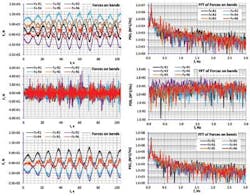
The following is an example of slug flow in a jumper, modeled with two-way fully-coupled fluid-structure-interaction (FSI). The simulations are on a generic geometry of a jumper.
Multi-phase flow in jumpers covers the complete flow map including slug, annular, dispersed, stratified, and wavy flow. The movement of the interfaces between different phases in the pipes must be accurately captured for simulation of FIV, thus a multi-phase model is required. The volume of fluid (VOF) multi-phase model available in STAR-CCM+ was used to simulate the transient behavior of the mixture and the development of slugs in the jumper. VOF uses the Eulerian framework and is a practical approach for applications involving two or more immiscible fluid phases, where each phase constitutes a large structure in the system.
One key to this is to address the need to understand the role FSI plays in the fatigue life of subsea structures. The open architecture in STAR-CCM+ helps provide answers because it seamlessly enables FSI simulations ranging from one-way coupling of either FIV or VIV all the way to two-way coupling, including both the internal mixture and external flow of the pipes.
The focus of the simulation is on FIV using co-simulation (fully coupled two-way interaction), where STAR-CCM+ handles the multi-phase flow and Abaqus FEA (SIMULIA) predicts the dynamic structural deformations of the jumper. The two domains are interconnected using the SIMULIA Co-Simulation Engine (CSE). Although this method is computationally intensive, it demonstrates a more general approach to the end user because it can be deployed for predicting the behavior of complex systems including non-linear structures and complicated geometries. Alternatively, because the generic jumper geometry is geometrically and structurally relatively uncomplicated (e.g., there is no contact with the seafloor), this simulation could also be done with a simpler approach by, for example, modeling the jumper with beam elements, using one-way coupling or completely performing the FSI problem in STAR-CCM+ using its structural stress analysis model.
In addition to direct co-simulation coupling with Abaqus, STAR-CCM+ offers users the ability to customize FSI simulations using JAVA to allow easy integration of their legacy codes or their FEA software of choice for FSI simulations.
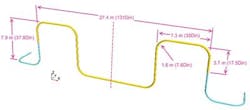
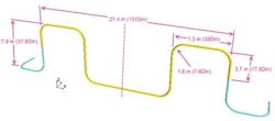
Computational jumper geometry
The generic jumper geometry here is made of steel, with a circular cross section and a traditional "M" shape. The jumper is clamped on both ends and the multi-phase flow through the pipes is a 50%-50% volume mixture of air and water (defined as stratified flow with water on the bottom and air on top at the inlet boundary). Fluid domain is extended compared to the deformable structure to avoid influence of boundary conditions on the flow inside the jumper.
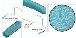
For the VOF mesh, the generalized cylinder mesher available in STAR-CCM+ was used with the polyhedral volume mesher. This works for this application because the geometry consists of cylindrical sections and the direction of the flow is parallel to the vessel wall. Using extruded prismatic cells reduces the overall cell count, ensures orthogonal cells and improves the rate of convergence. The final VOF mesh has ~4 million polyhedral cells.
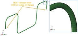
The Abaqus finite element model for the co-simulation consists of 21,000 four-node shell elements. First, a stand-alone structural modal analysis characterized the dynamic behavior of the structure. The stiffness in each coordinate direction was computed by applying a load to the pipe to get the resulting force-displacement relationship, and an eigenvalue analysis obtained the natural frequencies of the jumper. For this case, an equivalent mass representing both the mass from the flow inside the pipes (assuming a uniform mixture of air and water) and the added mass resulting from the displacement of the water surrounding the pipe was used. This added mass coefficient was taken from literature.
Displaying 1/2 Page 1,2Next>
View Article as Single page
