Manfred Sach • BJ Services Co.
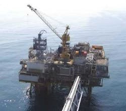
Coiled tubing (CT) technology is part of the offshore routine because of its efficiency, reliability, and effectiveness. For well cleaning and stimulation applications, CT offers technical and economic advantages compared with snubbing or bullheading.
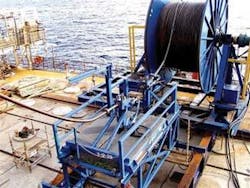
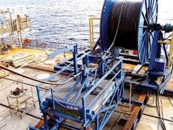
One fundamental advantage of coiled tubing is its continuous, non-jointed length; in some situations, however, this advantage can become a limitation. For some offshore wells, weight of the CT string required to safely and effectively accomplish a particular job may exceed crane lift capacity.
One solution to this problem is splitting the string and welding it together offshore. In the Norwegian sector of the North Sea, however, butt-weld failures on large-diameter [>2-in. (5.1-cm)] CT prompted the search for a viable, safer alternative.
The resulting connector technology has proven itself in offshore cleanout and stimulation operations, many of which would not have been feasible otherwise.
Avoiding welding
In the Norwegian North Sea, many wells are deep and/or highly deviated with large-diameter [7-in. (17.8-cm) or more] production tubing. In such wells, CT diameters of 2 3/8-in or 2 7/8-in. (6- or 7.3-cm) typically are required for operations that depend on high flow rates for effective stimulation or solids transport.
However, crane capacities or weather conditions often limit the weight of the CT string that can be lifted. In the past, CT service providers have minimized weights by using “split-reel” systems and thin-walled, high-strength parallel CT strings with constant wall thickness. For very deep cleanouts and for selective stimulation operations, service providers were forced to split CT strings into two (or more) lifts , then weld the strings together offshore.
However, orbital girth welds in CT butt joints typically achieve a low cycle fatigue (LCF) life in the range of 25 to 50% of the coiled tubing and require a large safety factor because of the large scatter in LCF life. For larger CT diameters, this leads to an unacceptably low number of safe trips available.
In addition, it’s not possible to visually monitor weak points near a butt weld after each run in order to make reliable decisions about the safety of continuing to run the string.
Instead, BJ Services developed the DuraLink spoolable connector, which splices two coiled tubing strings flush on the outside diameter of the tubing. In addition to being faster to install than a butt weld and requiring fewer personnel offshore, the resulting joint has a longer safe fatigue lifetime. The CT crew, following simple fit-for-purpose criteria, can visually inspect it after each run.
Other benefits include:
- Safer, faster, and more cost-effective than boat spooling, and less weather-dependent
- Torque, pull, axial, tensile, and compression load ratings that match the coiled tubing even after repeated cycling
- High- and low-pressure leak integrity
- Resistance to acid corrosion and H2S stress corrosion cracking
- Reduced personnel requirement on the platform – no specialized welders and inspectors needed.
This connector facilitates coiled tubing cleanouts in the large-bore wells typically encountered offshore Norway and also has seen application in other BJ operating areas. Being able to provide the correct size of CT avoids compromising job quality and represents a fundamental change in how CT operations are planned and conducted.
Of the first 17 operations performed using this connector, 15 had been considered unfeasible due to weight of the CT required.
During the bad weather, the maximum offshore platform crane limit may not be available for several weeks or even months, even if sufficient to lift the CT reel. In situations like this, the connector has been used to ensure that a platform’s operational schedule can continue by reducing the weight of the CT reels. Weight savings of more than 50% have been achieved.
The lifetime of this connector in the field compared well with experimental data. It is sufficiently high to enable multi-well campaigns without the need to replace the connector before operational objectives are achieved.
Selective stimulation
In one of the first “enabled” operations, it was used in a conventional bullheading acid fracturing operations to stimulate newly completed wells in Ekofisk. Ineffective fluid diversion and differences in fracture gradients along the wellbore meant that not all perforated zones were receiving stimulation. Production results were such that there was no need for alternatives to conventional acid bullheading.
This situation changed when production logs indicated that some key perforated zones in a new well were not contributing production. Knowing these zones were in productive pay and that no effective option existed for re-stimulating them from surface, a different approach was needed. A tapered, high-strength, 2 7/8-in. (7.3-cm) coiled tubing string could provide the required pressure rating and pump rates for selectively acid fracturing each individual zone.
However, the complete 2 7/8-in. (7.3-cm) CT drum needed weighed 110,000 lb (50 metric tons) Platform crane limitations required splitting the CT into two lifts and joining the segments offshore. Rather than weld the strings and compromise their lifetime for this acid pumping job, the DuraLink spoolable CT connector was used. One connector performed 13 runs, with little sign of wear. (The initial pressure test of the rig included the CT and connector being subjected to 8,400 psi (58 MPa).
The spliced coiled tubing with the fracturing bottomhole assembly was used to selectively straddle nine perforated zones in three wells, acid fracturing through the 2 7/8-in (7.3-cm) CT with pump rates as high as 16 bbl/min (2.5 cm/min) and pressures reaching 7,400 psi (51 MPa).
Results from these wells were generally above expectations and financially attractive: Production on the stimulated zones increased from 1,800 to 4,500 b/d (286 to 715 cm/d) of oil, with operational payback attained in five to seven days.
Furthermore, by selectively applying acid only at the perforated zones, the CT technology reduced the total acid volume for the job 50 – 80% compared with a typical bullheading.
Removing solids
The connector also enables a number of CT solids cleanout operations in deep wells where other technologies were unable to reach the bottom of the wells for effective solids removal. Even with the connector technology allowing longer reach, additional measures were needed to remove all of the solids from horizontal and highly deviated wells.
A multitude of factors influence solids transport, making it difficult to design and execute cleanouts in large diameter, deviated wellbores. In monobores with only one tubing size, it can be challenging to transport solids from a deviated/horizontal well section to surface due to low annular velocities.
Traditional cleanout tool designs affected the operations and results as well. Historically, well cleanouts involved running jointed pipe or coiled tubing to the bottom of the well and circulating fluid until clean returns were achieved. Inefficient cleaning often required additional CT runs or resulted in incomplete and unsuccessful cleanouts, especially in extremely long horizontals or highly deviated wellbores. The reason for this is that while tripping in, equilibrium solids beds form behind the BHA and along the wellbore. Circulation alone may be inadequate to remove those solids beds, and traditional cleanout methods did little to redistribute the equilibrium beds when pulling out of the hole.
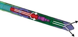
A new cleanout method specifically for deviated and horizontal wells was designed. The Tornado cleanout process combines a solids deposition and hydraulics model to predict solids transport along the complete wellbore, and a tool with a jetting nozzle that switches for forward- and backward-facing jets. When running in the hole, high-energy forward-facing jets break up and fluidize compacted fill. When pulling out of the hole, the tool can be cycled from surface so that fluid is forced through low-energy backward-facing jets which, under engineered flow conditions, sweep the solids from the hole. This sweeping action disturbs the equilibrium solids beds that formed behind the tool while tripping in, re-entraining the solids in the fluid and resulting in a more efficient and complete cleanout.
If needed, the tool can also be run on a BHA with a positive displacement motor (PDM) and mill without affecting cleanout efficiency.
Tripping speed and rates are critical to a successful cleanout, so a proprietary software with a unique solids transport module to optimize such job designs is used. Specialized field procedures allow the cleanout effectiveness to be verified during operation. Information gained from the verification process is used to make changes to the cleanout program as required during the operation.
One successful cleanout
The Tornado tool has been used in more than 1,000 operations worldwide, including more than 50 in the Norwegian sector of the North Sea, which are some of the largest completions in the world.
In an example, an operator was trying to add a new perforation interval to a North Sea well, but produced sand deposits in the deviated and horizontal sections of the wellbore prevented an electric wireline and tractor from reaching the required depth to set a plug above the existing perforations for isolation purposes.
The well had been originally completed with 7-in. (17.8-cm) tubing and casing down to 15,715 ft (4,790 m), with a 1,119-ft (341-m) section of 9 5/8-in. (24.4-cm) casing above the 7-in (17.8-cm) liner in the horizontal section of the well. The top of sand was estimated to be at a depth of 9,514 ft (2,900 m). In the well’s last cleanout intervention, two years before, a rig-assist snubbing unit and 3 1/2-in (8.9-cm) drill pipe encountered significant amounts of sand and scale.
The large [628 bbl (99.8 cm)] completion volume precluded specialized cleanout fluids for cost and logistical reasons. Therefore, the job was designed using only seawater and hydraulic friction reducer. Preliminary modeling with the solids-transport simulator indicated that pumping at the maximum rate through 2-3/8-in. (6-cm) CT while stationary at the bottom of the well would not remove enough solids to allow the wireline tractor to reach the required depth.
The final designed comprised four cleanout stages with four wiper trips. Wiper trip speeds were adjusted to accommodate transport of large solids particles discovered in the well. In each cleanout stage, the tool was run in to a predetermined depth with fluid exiting from the high-energy, downhole-facing jets penetrating through any solids, which then entrain in the circulating annular fluid. When the tool reached the required depth, the fluid stream was redirected to the backward-facing low-energy nozzles and the CT pulled up.
During this wiper trip, first solids were observed at surface when the tool reached a depth of about 4,921 ft (1,500 m). In all, the operation recovered some 6,000 to 8,000 kg (13,227 – 17,637 lb) of solids from the wellbore. After the cleanout, CT was used to install a full-bore mechanical plug. Electric wireline successfully perforated the new interval and also performed other subsequent operations.
