Alan Brodie
Petroleum Technology Co.
On most production facilities the number of industrial flammable gas bottles allowed on-site at any one time is kept to a low number. They are always stored away from locations where heavy lifting operations take place, where the risk of dropped objects increases dramatically. Potential sources of radiant heat are also avoided.
Consider, then, that the annulus of just one gas-lifted well can easily contain the equivalent of over 1,000 industrial-sized gas bottles. Even where downhole annulus safety valves (DH-ASVs) are deployed to minimize the capacity, the volume can still be the equivalent of more than 200 gas bottles per well. And heavy lifts are commonplace in well bays where annulus flowlines connecting the high-pressure lift gas supply header to each individual well are located.
The worst safety incident ever to occur in the North Sea was the Piper Alpha disaster in 1988. Release of lift gas from the well annuli was not the initial cause of the fire. However it did exacerbate the situation following annulus lift gas injection line failures, due to radiant heat from adjacent fires. This resulted in the ignition of high-pressure lift gas venting from well annuli, a situation which was made worse by the failure of the check valve in many of the downhole gas lift valves. Consequently many of the wells flowed naturally via the tubing/production casing annulus and then into the well bay via damaged gas lift injection lines, where the effluent was ignited.
Well integrity concerns
With all of this in mind, and the recent focus on well integrity following the Macondo incident, many major operating companies are looking to eliminate the well integrity compromises that have previously existed in their gas lift well designs, with particular with regard to:
- Gas lift check valves, which were never designed to be leak tight and were also proving unreliable, thus compromising the integrity of the primary well containment envelope (the tubing string)
- The risk of high pressure gas venting from the annulus in the event that the HP lift gas flowline or wellhead fixture to the annulus is damaged.
It’s amazing that the industry has taken so long to respond to these risks. Various API and ISO documents have until now only highlighted the issue, without specifically addressing it. For instance ISO 17078-2 “Flow control devices for side-pocket mandrels” states:
“These devices are designed and intended to prevent reverse flow through a flow control device. They are not designed nor intended to provide a tight shut-off pressure safety seal or to be a part of the safety system.”
The same is generally true of DH ASVs. In most cases they do not provide a 100% barrier to flow or a tight shut off safety seal.
ALARP requirements
The industry worldwide is largely self-regulated regarding well integrity. Operating companies are required to demonstrate that the risks of hydrocarbon release are as low as reasonably practicable (ALARP) by “using the best equipment, and industry best-practice.”
To keep risks ALARP in gas lift completion designs, new technologies have been developed and are increasingly being adopted, namely:
- Downhole gas lift valves, which could be relied upon to provide a “well integrity barrier” throughout the life of the well, thus maintaining the integrity of the primary well containment envelope
- Actuated wellhead safety valves, located within the body of the wellhead, can be relied upon to close in the event of damage to the HP lift gas flowline. This assures the integrity of the secondary well containment envelope and significantly reduces the inventory of gas that could vent in the case of a HP gas lift line failure.
Conveniently, these technologies can be readily retrofitted, without the need for expensive workovers.
In 2010, Statoil published a paper at OTC on improving gas lift valve reliability. It described its new validation program based on standards used for packers and plugs (ISO 14310:2008), which has a leak criterion (for gas) of 20cc/10 min.
It also states: “Strong evidence from both the lab and the field suggest that the valve developed to the validation program is considerably more robust and has an extended lifetime in harsh conditions. The increased robustness and lifetime will increase the safety level of the well and reduce intervention time and cost.”
A number of “well barrier” downhole gas lift valves now available meet the ISO 14310 factory acceptance test (FAT). However, gas lift valves are invariably exposed to erosive fluids at some time. Consequently some operating companies are insisting that FAT testing should be repeated after flowing erosive fluid through the valve.
PTC developed Safelift gas lift valves (GLVs) in response to the industry’s demand for such a valve. They have been tested and verified ISO 14310:2008 following the circulation of up to 600 bbl of water at up to 3 bbl/min with up to 4 kg/cu m of barite. We believe this is a unique capability – these valves are designed to provide integrity for the life of a well, not just to pass an FAT.
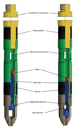
These valves are essentially modular. All valves in the family incorporate the same check valve module. These were designed using computational fluid dynamics to ensure the check valve flow paths and the opening dimensions were optimized with respect to erosion across the metal/metal seal faces.
The orifice or gas lift valve choke also moves with the check valve as it opens, which significantly reduces chattering. And finally, the check valve spring location (around the dart) and size allows for it to be more robust than on traditional valves, requiring an opening pressure differential across the valve orifice of 25 psi (1.72 bar).
In a traditional gas lift check valve design, the flow stream usually impinges directly on the check valve seal face, which is normally held in place using a relatively lightweight spring which leads to a relatively small valve movement. As a result, erosive velocities across the valve seal faces are high and the valves have a tendency to chatter. Both of these conditions result in premature seal failure. The Safelift check valve design, however, addresses these shortcomings and as a result valve performance, reliability, and longevity is superior.
The injection pressure operated (IPO) unloading valves employ a unique, bellows unloading valve module. The bellows are rated to 10,000 psi (689 bar), which facilitates very deep gas lift valve deployment. Despite this high pressure rating, the bellows are much less stiff than traditional bellows, allowing for unusually long valve stem travel.
Unlike traditional valves, the function of the bellows is not to provide the force to hold the valve closed on its seat. Instead, a spring is used to hold the valve closed (the bellows serves to retract the valve off seat). In the event of dome pressure loss or bellows failure, the unloading valve is designed to fail-safe in the closed position. In any case, since the valves employ metal/metal seal N2 domes and pressure-balanced edge welded bellows, the likelihood of dome pressure loss in these valves is low.
The bellows OD is also larger than that used in traditional gas lift valves; and, as a result, the valves are less sensitive to tubing pressure variations. The unusually long bellows travel also means the valve suffers very little from throttling and the unloader module is essentially invisible to flow when fully open. Consequently, shallow-set Safelift IPO unloading valves are now being deployed for long-term gas lifting (essentially as a back-up operating valve in cases where operating conditions change unexpectedly), without concerns of accelerated time to failure.
PTC’s Safelift gas-lift valves.
SAS Valves
PTC’s actuated SAS valves offer protection against the release of a large volume of high pressure lift gas from the well annulus if the surface lines are damaged. The check valve design is similar to that employed in our gas-lift valves, providing higher integrity and reliability than traditional gas lift line check valves. The SAS range is designed and tested in accordance to API 6A PSL 3G PR2, and fire tested in accordance to API 6FB and API 6FD, exceeding the testing criteria by achieving V0 (zero bubbles) with gas as test medium.
The valves are actuated (held open/fail-safe closed) using the christmas tree ESD system. Consequently they are not prone to wear and tear due to chattering in fluctuating gas delivery conditions. This means that the valve seal faces are protected, remaining in excellent condition, when sealing is required.
It is designed to be installed inside a VR profile within the wellhead. The modular design of the M-SAS allows detachment on severe impact, leaving the check valve undamaged and intact in the VR profile. The H-SAS is an integrated actuator version of the valve. It is used in cases where the wellhead flange is long enough to accommodate both the VR check valve and actuator in one assembly.
Offshore Articles Archives
View Oil and Gas Articles on PennEnergy.com


