John Murray, Terje Eilertsen, Chris Barton - FloaTEC, LLC
Selection of a floating hull type can depend on a number of factors. For instance, the primary reasons operators select a Dry Tree Unit (DTU) are for well intervention and riser response. Well intervention costs can represent 40-50% of opex. These costs can be reduced significantly using a dry-tree approach and using a workover or drilling rig for well intervention. Waiting on an available Mobile Offshore Drilling Unit (MODU) for well intervention can increase well downtime. DTUs provide the opportunity to re-enter a well at any time. Some experts claim that as much as 25% of additional reserves can be recovered by using dry trees vs. wet trees.
Whether the hull type is a spar, TLP, or semi, efficient design of floating structures is predicated on functionality and performance. It should be capable of supporting the necessary equipment for drilling and production, while also meeting all performance and safety-related criteria. The floating structure should provide sufficient space and robustness to fulfill its intended purpose and it should be built at a minimum of cost, which is governed mainly by the hull’s steel weight.
Hull selection
Selecting a hull form is guided by criteria such as operating environment, subsurface characteristics, availability of fabrication facilities, suitability to the operator’s development plan, and sometimes an operator’s preference for a certain concept.
Hull weight estimates are based on global sizing which is determined by the naval architectural and structural design. Global sizing is a key engineering process in both the concept selection and follow-on design phase of a floating structure. The sizing of a moored floating structure considers relationships between payload, hull size, and mooring system. During concept selection, efforts concentrate on the main dimensions and weights with respect to design standards and performance requirements without a high degree of engineering detail. Final dimensions and properties of the hull will be determined in the FEED stage through various analyses.
Well and completion design are governed by subsurface characteristics. Designing a fit-for-purpose floater considers whether it will support dry or wet trees, require future expandability, and its function as a production hub or wellhead platform. Some physical considerations taken into account when selecting a floater are hull steel weights in relation to supported payload, the overall performance in a particular environment (which has a direct impact on tensioning systems if a dry tree unit is selected), and marine operations required for installation, and hook-up and commissioning.
For deepwater floating production systems, certain considerations influence the selection of a concept:
Small in-place motions to enable dry tree production and drilling risers. The economics of a DTU, particularly in view of the present-day availability and cost of deepwater MODUs, can favor systems that can drill and complete wells from the same platform. Both the TLP and spar have dry-tree capability.
Large, open-deck areas to enable more efficient operations. This allows for good ventilation, lay-down areas, and equipment arrangements on a single-deck elevation. The semi and TLP are more adaptable to large footprints and open areas. Because of the single caisson footprint architecture of the spar hull, the topside equipment has to be stacked several decks high.
Quayside integration to enable installation and commissioning of topsides on the floating hull at a quayside location. This reduces cost and mitigates risk associated with offshore operations since it eliminates the need for heavy-lift equipment. Quayside integration requires a floater to have adequate stability at a shallow draft. The semi and TLP have an advantage over the spar in this regard.
Water depth sensitivity to enable a range of water depths given the additional buoyancy requirements related to increased mooring and riser loads as water depth increases. The spar and semi are less sensitive to water depth, whereas the current limit for TLP technology is around 5,000 ft, governed mainly by the tendons.
| Spar | ETLP | Dry-Tree Semi | |
|---|---|---|---|
| Small in-place motions | Can support TTRs and SCRs, accelerations at deck level higher than ETLP and Dry-Tree Semi. | Can support TTRs and SCRs, require catenary mooring to assist in offset control. | Can support TTRs and SCRs. |
| Large open deck areas | Because of small footprint from single column hard tank, deck is multi-level. | Can support large open deck areas, steel savings in smaller deck span. | Can support large open deck areas similar to conventional semisubmersibles. |
| Dockside HUC of topsides | Because of deep-draft, Spar must be towed horizontally to installation site. | Topsides can be installed and commissioned dockside. | Topsides can be installed and commissioned dockside with heave plate retracted. |
| Water depth insensitivity | Covers a wide range of depths and payloads. | Limited to water depth of around 6,000 ft with standard tendon design. | Covers a wide range of depths and payloads. |
| Minimum at-sea commissioning | Requires heavy-lift vessel for single or multiple module lifts. | Requires installation on pre-installed tendons, can be difficult where swell persists. | Can be installed on preset moorings. |
| Redeployment | Within limited water depths, sufficient to tow hull in vertical orientation. | Difficult to disconnect from tendons. | Can be returned to dockside for refit and redeployment. |
Spar technology
The first spars were based on the classic caisson design. This evolved into the truss spar by replacing the lower section of the caisson hull with a truss. Spars are ideal as DTUs because of their small vertical motions. Dry trees provide direct vertical access to the wells, which allows the spar to be configured for full drilling, workover, production, or any combination thereof. One of the distinctions of the spar is that its center of gravity (CG) is always lower than the center of buoyancy (CB), hence its stability. The spar derives no stability from its mooring system, so it will not list or capsize even when completely disconnected from its mooring. The deep-draft is a favorable attribute for minimizing heave motions - its draft and large inertia filter wave frequency motions in all but the largest storms. The natural period in heave and pitch are above the range of wave energy periods. The long response periods for spars mitigate the mooring and riser dynamic responses common with ship-shaped FPSOs and semis. The deep-draft, along with the protected center well, also reduces the current and wave loading on the riser system. These loads normally control the tension and fatigue requirements of the production risers on TLPs.
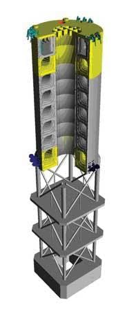
The truss spar is characterized by a hard tank compartmentalized to house void tanks and variable ballast tanks, a truss section with a number of heave plates, and a soft tank at the keel to hold fixed ballast. The hard tank provides sufficient buoyancy to support the topsides, hull structure, and moorings. The heave plates provide added mass and damping, which gives the spar a heave natural period of around 30 seconds. The water plane area inertia makes a small contribution to the metacentric height (GM), which is controlled primarily by the distance between the CB and CG. The GM is a characteristic of a ship which helps determine its stability in water. The CG is kept low by installing fixed ballast in the soft tank. The spar is moored using a spread catenary system which generally is pre-installed before the hull arrives.
The main design features of the spar are: high heave and pitch natural periods greater than 25 seconds (without risers), maximum offset of 7-9% of water depth in damaged condition, maximum heel angle less than 10° in intact and damaged condition, wet-tow draft shallow enough to offload the hull from a dry transport vessel, and adequate structural strength for up-righting during installation.
Buoyancy cans typically support the risers in wet centerwells. New designs use hydro-pneumatic tensioners. When these are used, the weights of the risers are borne by the buoyancy in the hull. As the number of risers increases, the tensioners increase the heave stiffness of the spar, which reduces the heave natural period. The total tensioner stiffness is designed to have a heave period high enough above the wave periods to avoid resonance excitation. Buoyancy cans in the open centerwell do not effect the heave period. However, they are difficult to install once the topsides are in place. Buoyancy cans are installed before the topsides, whereas hydro-pneumatic tensioners can be installed as the wells are tied-back and completed.
New spar hull designs
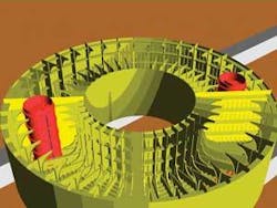
FloaTEC, LLC is developing new spar hull designs in an effort to improve the technology. Its Ring Spar design offers improved architecture for the hard tank internals. The hull does, however, maintain the unique motion characteristics of the truss spar, as the outside of the hull remains unchanged. The new structural design provides for some potential weight reduction in the hard tank section, as well as potential gains in yard productivity, compared to traditional stiffened plate configurations. The hull design has an integrated framing system between shells and flats. The primary girder stiffening of the outershell, centerwell, and flats is configured as a rigid-frame system. These girder frames are arranged in a radial pattern so they can be identical in a compartment. In this configuration, there are no global ovaling or complex girder buckling issues since the longitudinal girders span directly from flat to flat. Horizontal decks and radial bulkheads divide the hard tank spaces into tanks and voids. The lower set of tanks is configured to contain seawater ballast, which can be increased, decreased, or moved between tanks for major changes in topside weight and eccentricity, SCR weight, or hull flooding resulting from damage. At the waterline, an additional set of internal rings are provided as a cofferdam, thus controlling the set in a hull damage load case.
Another new design, the DryCenterwell Spar, is in the works. This is a design whereby the centerwell is closed to provide additional buoyancy. Early studies indicate there are technical advantages to this new design. For example, the dry centerwell design is more amenable to asymmetric wellbay layouts and enables a smaller diameter for equal payload, thus reducing mooring loads and size.
Cross-section of the Ring Spar’s hull.
FloaTEC is also developing a Gulf of Mexico-based delivery model to eliminate the cost and schedule time associated with dry transport from overseas.
Responding to market
FloaTEC is involved in a number of initiatives to drive down costs and delivery time. As outlined above, its Ring Spar technology offers a more fabrication-friendly design, while its DryCenterwell technology incorporates features that will enable more design and construction flexibility.
Also, given increasing MODU costs with small windows of availability, the company is investigating a dedicated drilling spar design and is developing dry-tree semi technology. Other areas under study include floatover installation methods to eliminate the need for heavy-lift vessels for topside installation for spars, redeployment of floaters for multiple uses, and lease-back arrangements.
The company is prepared to finance projects via structured shared ownership agreements.
A general description of criteria for selecting a particular hull form are qualitative and based on a number of general considerations evaluated in the selection process. The capacity of the three hull forms to satisfy these criteria is summarized in the table at left.


