Pressure requirement is key consideration
Joe Cheema
Fluid Energy Controls
Gushers may look great in films like 2007’sThere Will Be Blood, but like many of Hollywood’s ideas, they are far better on the screen than in real life. Fortunately, drilling is much safer since 1922 when James Smither Abercrombie walked into Harry Cameron’s machine shop in Humble, Texas, and explained his idea for a ram-type blowout preventer. Cameron was dead within six years, but Cameron International Corp, now a $5-billion Houston-based international flow equipment firm, still makes BOPs. The designs, of course, have advanced considerably over the years, and Cameron offers dozens of models designed to prevent surface and subsea blowouts on different sizes of drill pipes. That company has been joined by a dozen or more BOP manufacturers such as Hydril and National Oilwell Varco/Shaffer.
Whether you are using an annular BOP, a blind ram, a shear ram, or any combination of devices in the BOP stack, they are only as safe, effective, and reliable as the hydraulics that drive them. The accumulators storing the hydraulic fluid must be appropriately sized for volume, speed, and pressure.
Types of accumulators
An accumulator is essentially a pressure vessel that stores the hydraulic pressure needed to close the BOP in the event of a blowout. The amount of pressure required varies depending on the type of BOP. Annular or spherical BOPs, usually the first line of defense against a blowout, require a far lower pressure than a shear ram which is intended to cut through the drillstring. While the original Cameron BOP operated at 3,000 psi, a remarkable figure for the time, today pressures run as high as 15,000 psi, and 20,000 psi is well into development.
There are several types of accumulators to be considered for application in conjunction with BOPs. The following describes these and explains which work best for BOPs and why:
Spring accumulators – Use a spring-loaded piston in a cylinder. As the oil line pressure increases, more oil flows into the cylinder to compress the spring until the spring pressure matches the hydraulic pressure. Then, when the pressure drops, the spring forces the oil back out of the cylinder into the system. Spring loaded accumulators have three primary shortcomings. As the spring expands, pressure gradually drops rather than remaining constant. Since these types of accumulators have moving parts, those parts do wear and need replacement. In addition, repeated compression and expansion of the spring fatigues the metal and reduces the amount of pressure the spring can provide. This limits usefulness in high-cycle applications as the metal fatigues and loses its elasticity.
Gravity-loaded accumulators – These are similar to the spring accumulators but, instead of a spring, these use weights to drive the piston and to provide the desired pressure. The advantage is that it supplies a near constant pressure. It is, however, larger, heavier, and more costly than other types of accumulators. In addition, it has moving parts that require maintenance. If the packing on the piston wears and develops a leak, oil gradually migrates to the top of the piston, adding to its weight and reducing the effective amount of oil in the accumulator.
Gas-loaded accumulators – There are several types of accumulators that use compressed gas to provide the pressure. These divide into two main categories: separator and non-separator accumulators. Non-separator accumulators do not have a barrier between the gas and the liquid. This is the simplest design and can store the greatest amount of oil. However, its drawbacks make it unsuitable for use with a BOP. Since there is no barrier separating the gas from the oil, the gas may be absorbed by the fluid, particularly at higher pressures. Then, as the pressure drops, the absorbed gas forms bubbles in the oil, causing sponginess in the system and possibly damage to the equipment through cavitation.
Bladder-type accumulators – The type of accumulator that is proven best for BOPs is the bladder accumulator. The BOP control unit contains up to a several dozen accumulators of 10 gal or larger size. The accumulator vessels are made of carbon steel designed to withstand pressures in the range of 3,000 psi. Inside is a bladder made of nitrile compound (BUNA-N) or other material as appropriate. Because of its high flexibility and low weight, the bladder has a very rapid response time, allowing the accumulator to close the BOP in less than a second. If the working pressure will be below 500 psi, a screen can be welded inside the flange to keep the bladder from extruding through the fluid port. At higher pressures, the bladder may extrude through the screen, so a plug and poppet assembly is used. As the pressure drops, the bladder pushes against the poppet to close the fuel port, keeping the bladder inside the vessel.
Bladder-type accumulators are installed vertically with a gas valve molded into the top of the bladder and a fluid port at bottom of the vessel. The bladder is pre-charged to 70-80% of the minimum working pressure of the system, and this pressure must be verified periodically. Typically, nitrogen is used because it is very stable and non-reactive, even under pressure. Air is not a good choice because of its corrosive properties and risk of explosion under high pressure.
By selecting the proper size accumulator and properly maintaining it, operators can avoid the injuries, and costly and catastrophic damage caused by blowouts. Given the number of things that can potentially go wrong, whether through natural events, or component or human failure, correctly designed and maintained accumulators are an easy means of gaining a little margin of safety.
Sizing the system
Selecting the right size accumulator and the correct pre-charge pressure requires an understanding of the underlying principles. Bladder accumulators operate based on Boyle’s Law, which states that the product of the pressure (P) and volume (V) of a fixed quantity of gas is a constant (C), assuming the temperature remains constant (PV=C). In simple terms, if you double the pressure, you halve the volume. Since the expansion and contraction of the bladder take place in under a minute, however, there is no transfer of heat into or out of the gas as the pressure changes. As a result, the formula for a nitrogen charged bladder becomes P1V11.4=P2V21.4 .
Applying this data to the sizing and operation of an accumulator, results in the following:
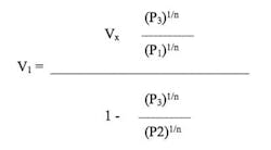
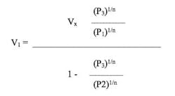
V1 = Size of the accumulator required in cubic inches. This is the maximum volume of gas in the accumulator bladder at the pre-charge pressure P1.
VX = The volume of lube oil to be discharged from the accumulator in cubic inches. This the volume of lube oil demanded by the system. The VX value is a function of the lube oil system for a particular type of turbo-machinery and can be obtained from the manufacturer’s specifications.
P1 = Pre-charge gas pressure of the accumulator in psia. This pressure is always less than the minimum system pressure P3.
P2 = Maximum system design operating pressure in psia.
V2 = Compressed volume of gas at maximum system pressure P2, psia.
P3 = Minimum system pressure, psia, at which the additional volume V3 of lube oil is required.
V3 = Expanded volume of gas at minimum pressure P3 in cubic inches.
Here is how this applies to sizing an accumulator for a BOP that requires a flow rate of 15 gpm at 1,500 psig system pressure and a maximum operating pressure of 3,000 psig. If the main oil pump shuts down, system pressure must be maintained within 10% of the system pressure for 15 seconds while the stand-by pump accelerates from idle to operating speed.
In this case, the volume of fluid needed by the accumulator is Vx = (15 gpm / 60 sec) x 15 sec x 231 (cu in/gal) = 866.2 cu in.
Minimum system pressure (within 10% of the system pressure):
P3 = (1,500 x 0.9) + 14.7 = 1,350 + 14.7 = 1,364.7 psia.
Maximum operating pressure:
P2 = 3,000 + 14.7 = 3,014.7 psia.
Polytropic constant for Nitrogen: n = 1.4.
Pre-charge pressure of the accumulator (at 75% of working pressure):
P1 = 75% of P3 = 0.75 x 1,364.7 = 1,023.5 psia.
Inserting these values into the formula below gives the size of the accumulator required (V1):
This formula yields a volume of 2,461.4 cu in., or 10.7 gal.
The accumulator comes in that exact size, so the next larger size should be selected, not the next smaller one. There is no harm in being able to provide additional oil when needed, but there is a risk of damage if the undersized accumulator runs out of oil too soon.


