Design procedures for deepwater fluke anchors, drag-in plate anchors
Many parallel efforts are being made to develop procedures and analytical tools required for design of mooring and anchoring systems for deepwater. Anchors represent a vital component for the safety of the mooring system as installed, and the safety requirements for floating production units are higher than for drilling units. For floating production units with catenary mooring systems, the choice has been between fluke anchors, suction anchors, and pile anchors.
As oil and gas exploration and production moved into greater water depths, conventional catenary mooring systems (CMS) became too heavy. This has led to the introduction of taut mooring systems (TMS) with synthetic fiber ropes instead of wires and chain. Besides the lower weight of a TMS, this system provides an additional advantage of reduced offset (improved stationkeeping capability) during extreme environmental conditions and significantly reduced footprint at the seabed.
In a taut mooring system, the anchors need to be designed for significant vertical load components. The uplift angle of the mooring line at the seabed may be in the range 30-40° in TMS, the uplift angle being controlled (reduced) by use of chain segment near the seabed. Since conventional fluke anchors are suitable for use mainly in CMS, the manufacturers of fluke anchors developed a new anchor concept aimed specifically in TMS deployment.
In view of the difference between conventional fluke anchors and these new type of anchors, the generic name "vertically loaded anchor" (VLA) came into use. In retrospect, it is unfortunate that vertically loaded anchors should be associated with only one type of anchors, since other types of plate anchors, such as suction anchors and pile anchors, can take significant vertical loads. Therefore, the VLAs are called drag-in plate anchors in the DNV Recommended Practice RP E-302. This terminology can then be extended to other types of plate anchors like push-in plate anchors, drive-in plate anchors (used by US Navy), and suction embedded plate anchors (SEPLA) (see article in Offshore March 2000), which are in various stages of development.
The following includes a brief description of the design procedures recommended by DNV for fluke anchors and drag-in plate anchors.
Fluke anchors
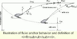
The anchor penetration path and the ultimate depth/resistance of the anchor are significantly affected by the type (wire or chain) and size of the forerunner. The resistance of an anchor depends on the ability of the anchor to penetrate and reach the target installation tensionTi. At the ultimate penetration depth zult the anchor is not penetrating any further. The anchor is "dragging" with a horizontal, or near horizontal fluke, and the tension in the line is constant. At the ultimate penetration depth, the anchor reaches its ultimate resistance Rult.
The most rational design strategy is to assume that the anchor is not penetrated tozult, as illustrated by the intermediate penetration depth. This will also lead to more predictable drag, and should drag occur, the anchor may have reserve resistance, which can be mobilized through further penetration.
A non-zero uplift anglea at the seabed can be acceptable during the extreme environment, provided that the anchor is penetrated deep enough to resist the vertical component Tv. A new generation analytical tool called Digin has been developed as part of the DNV DeepAnchor JIP, which is used to predict the anchor behavior duRing penetration and operation, while accounting for the interaction between the anchor/ anchor line, the soil, and the line tension. Digin, which is calibrated against full-scale anchor tests, is also used for prediction of the behavior of drag-in plate anchors.DNV RP-E301design
According to the DNV design procedure for fluke anchors, the characteristic anchor resistanceRC is made up of two main components:
The installation anchor resistanceRi is known with the same confidence as Ti, and the partial safety factor is set so it equals 1.0 under the assumption that the installation tension is measured with sufficient accuracy (by use of the DNV Tentune method). If it cannot be documented that the specified minimum installation tension Tmin at the line touchdown point has been achieved, the partial safety factor on Ri will have to be set higher than 1.0.
The design line tensionTd at the touch-down point is the sum of the two calculated characteristic line tension components, TC-mean and TC-dyn, at that point, multiplied by their respective partial safety factors gmean and gdyn, (for example) Td = TC-mean . gmean + TC-dyn . gdynwhere:
TC-mean = the characteristic mean line tension due to pretension (Tpre) and the effect of mean environmental loads in the environmental state
TC-dyn = the characteristic dynamic line tension equal to the increase in tension due to oscillatory low-frequency and wave-frequency effects
In accordance with the safety requirements according to the limit state method of design requires the following inequality must be satisfied for both limit states:
Rd greater than or equal to Td
The geotechnical design of the anchors shall satisfy both the ultimate limit state (ULS) for an intact system, and the accidental damage limit state (ALS) for one-line failure. In addition, two consequence classes are defined to account for the consequence of anchor failure in the actual case. The partial safety factors recommended DNV RP-E301 are temporary, until a formal reliability study has been carried out.
If the anchor is installed with an uplift angle, and uplift is assumed also for the design event, the length of line on the seabed will be set to zero (for exampleLs,i = 0 as assumed in Eq 2 Tmin the necessary minimum installation tension becomes
Tmin = Td - (DRcons+ DRcy)/gmFluke anchor issues
The following key issues should be addressed for design and installation of fluke anchors:
- Range of soil conditions for the mooring pattern, and variations between anchor locations
- Seabed topography
- Selection of type and size of forerunner
- Selection of fluke angle for the actual soil conditions
- Prediction of anchor penetration path and effects of consolidation and cyclic loading
- Selection of installation scenario (maximum bollard pull)
- Installation with uplift angle
- Target installation depth versus predicted ultimate penetration depth
- Measurements during installation (installation tension, for control of design assumptions).
Drag-in plate anchors
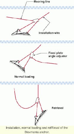
This anchor is installed as a conventional fluke anchor and when the target installation tensionTi has been reached, it is triggered to create normal loading against the fluke (plate). In this normal loading mode, the anchor acts as an embedded plate with a high pullout resistance Rp. Examples of drag-in plate anchors are the Denla anchor and the Stevmanta anchor. Well-instrumented on shore tests carried out with both these anchors in 1998 have provided valuable data for understanding the behavior of these anchors during installation, triggering, and pullout.
The pullout resistanceRp of a drag-in plate anchor depends on the ability of the anchor to penetrate and to reach the target installation tension (Ti). The predicted ultimate penetration zult of the anchor is crucial for sizing the anchor, given Ti and the shear strength profile. It is important not to overestimate zult. The design (sizing) of the anchor should assume that the anchor is installed to a depth zi, which is significantly less than zult (the same strategy as recommended for fluke anchor design). In addition, the minimum penetration depth zmin is set to 4.5 fluke widths (WF) to ensure that the boundary conditions for assuming deep failure are satisfied in the computation of the anchor pullout resistance.
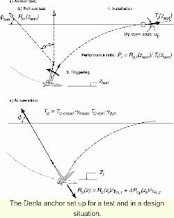
The assessment of the target installation tensionTi is a crucial design issue, which is directly related to the anchor performance ratio Pr. The performance ratio Pr expresses the relationship between the pullout resistance Rp in the loading direction normal to the fluke plane and the target installation tension Ti.
The above sketch shows a typical anchor test situation, where the anchor, in this case a Denla anchor, is pulled in to a penetration depthztest, applying a line tension Ti(ztest) and an uplift angle ai. After triggering of the anchor, a pullout test is performed, which gives the installation pullout resistance Rp,i(ztest). The performance ratio Pr is defined asPr = Rp,i(ztest)/Ti(ztest)
The installation pullout resistance measured in an offshore test includes a loading rate effect, which is expressed by a loading rate factorUr. By dividing the measured Rp,i(ztest) by this loading rate factor, one can obtain the static pullout resistance RS(ztest) at the test depth ztest.
RS(ztest) = Y.Rp,i(ztest)where
Y = inverse loading rate factor (= 1/Ur), which accounts for the strain rate effect on the undrained shear strength su, when comparing an offshore pullout test with a static pullout test (typically Y = 0.8 for soft clay)The cyclic loading effect on the static undrained shear strength of soft to lightly overconsolidated clay, and consequently on the static pullout resistance of an anchor in that clay, may be expressed by a cyclic loading factorUcy. This provides the following expression for prediction of the target installation tension Ti(zi), which is relying on the anchor performance ratio Pr obtained from site-specific anchor tests, assuming the anchor installation depth zi=ztest.
Ti(zi) = Y.Ucy . Rp,i(ztest)/PrIf the depth of the anchor testztest is significantly different from the installation depth zi, corrections for this difference must be made.
DNV RP-E302 design
Anchor pullout resistance is split into a static componentRs(zi) and a cyclic component DRcy(zi).Rs(zi) = Nc . Sc . h . (su,0 + k(zi)) . AflukeDRcy = Rs(zi) . (Ucy . -1)where
Nc = bearing capacity factor (Nc = 12.5, plane strain)
Sc = shape factor (Sc = 1.1 for assumed fluke width/length ratio Af = 0.5)
h = empirical reduction factor from field tests, which accounts for effects of soil remolding, strain softening, out-of-normal and eccentric loading of the plate (typically h = 0.70-0.75)su,0 = undrained shear strength seabed intercept
k = undrained shear strength gradient(s) between seabed and installation depth zi
Afluke =
The expression for the design pullout resistance then becomes:
Rd(zi) = Rs(zi)/gm,1 + DRcy(zi)/gm,2= Rs(zi){(1/gm,1) + (Ucy -1)/gm,2}wheregm,1 and gm,2 are partial safety factors. Td = TC-mean . gmean + TC-dyn . gdynprovides the design line tension Td, and the requirement is that Rd(zi) greater than or equal to Td as given by Rd greaterthan or equal to Td. Reference is made to RP E-302 for more details regarding the practical application of the described design method.Drag-in plate anchor issues
The key issues for design and installation of drag-in plate anchors are much the same as those given for fluke anchors above. In addition, the following issues are relevant:
- Assess applicable anchor performance ratioPr for the actual soil and anchor
- Evaluate need for site specific anchor tests
- Assess long-term anchor creep during service-life, if relevant.
Design methodologies for other types of plate anchors, like push-in plate anchors, drive-in plate anchors, and suction embedment plate anchors, should be established with due consideration of the characteristics of the respective anchor type. However, the design procedure DNV RP-E302 for drag-in plate anchors may be used (with caution) as a guidance for assessment of the pullout resistance also of other types of plate anchors.
References
For a complete list of references, please contract Rune Dahlberg by E-mail at [email protected].

