Truong Tuan Anh
Luong Duc Phong
Dang Hong Thong
Cao Le Duy
Cuu Long Joint Operating Co.
Dian Permanasari
Charles Fulton
Nora Yusuf
Carlos Maeso
Gagok Imam Santoso
Phung Nguyen Thanh
Moet Moet Lwin
Dennis Miguel
Schlumberger
Recently, the Cuu Long Joint Operating Co. (CLJOC) deployed a couple of fit-for-purpose well placement solutions offshore Vietnam that have enabled the venture to enhance production and improve recovery.
These fit-for-purpose well placement solutions included the first ever deployment offshore Vietnam of advanced distance-to-boundary (DTB) mapping and resistivity-at-the-bit logging-while-drilling (LWD) tools.
These solutions also involved thorough pre-job planning, real-time interpretation, and careful execution. They were developed for two wells in an effort to address the challenges of targeting new oil prospects. For the second well, the LWD tools helped to avoid the need for a pilot well.
Cuu Long Prospect
The Cuu Long Prospect (CLP) oil field is located in the Cuu Long basin offshore Vietnam. It is operated by CLJOC, a joint venture of PetroVietnam Exploration and Production Co. (50%), ConocoPhillips (UK) Cuulong Ltd. (23.25%), Korea National Oil Co. (14.25%), SK Energy (9%), and Geopetrol (3.5%).
The field was discovered in 2001 and started production in 2003, initially from a fractured granite basement sourced by lacustrine shales deposited during the middle and late Oligocene. Subsequently, reservoirs in the overlying Oligocene C30 and Lower Miocene B10 sands have been developed. The current production rate is approximately 33,000 b/d from 25 producing wells; however, this rate has been declining over recent years. To reverse this trend, CLJOC is exploring potential new prospects.
During the course of exploration and development drilling, thin oil-bearing sands were identified in the Lower Miocene and Upper Oligocene that CLJOC decided to develop. However, there were large uncertainties regarding reservoir thickness and lateral continuity. Hydrocarbon content was untested, and there was low confidence in the depth conversion of the top of the structures interpreted from the seismic data. It was initially planned to drill two horizontal wells, both with pilot holes. The main challenges were to reduce the depth uncertainties for landing the producer well, test the hydrocarbon content, and maximize reservoir contact in the thin sands. Pilot holes are expensive, and CLJOC was interested in alternative solutions.
Pilot well ST-A-ST2
The first well was drilled as a side track from the unused CLP SW basement injector ST-AI. This pilot well was designed to test reservoir quality and hydrocarbon content and resolve depth uncertainty in the Lower Miocene B10, B15, and B40 sands. Subject to the results, a production well would then be drilled as a side track in one of these reservoirs targeting whichever sand was expected to deliver the best oil production rate.
The LWD program for the ST-A-ST2 pilot hole consisted of gamma ray (GR) and resistivity in the 121⁄4-in. hole section and triple-combo (GR, resistivity, density, neutron-porosity) measurements in the 81⁄2-in. section. Based on the results of these measurements, the operator decided the production well should target the thin—2 to 3 m (6.5 to 9.8 ft) true vertical depth (TVD)—B15 sand.
Production well ST-A-ST3
The bottomhole assembly (BHA) for the 6-in. production well that was drilled as a side track from pilot well ST-A-ST2 included a rotary steerable system (RSS), near-bit GR measurements, and traditional triple-combo LWD measurements for formation evaluation. The RSS allowed continuous rotation of the drillstring while steering the well, providing optimum drilling efficiency, maximizing rate of penetration, and minimizing time spent on dedicated hole-cleaning trips.
The BHA also included the PeriScope deep azimuthal electromagnetic resistivity distance-to-boundary mapper. During drilling operations, these LWD measurements were transmitted in real time to the surface to support real-time decision-making to optimize geosteering of the well. The service was used to map the structure around the wellbore to help identify the reservoir sand and its overburden while drilling and to help keep the horizontal section within the high-permeability pay zone.
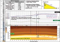
The PeriScope bed boundary mapper makes 360° deep directional measurements that can indicate the distance to—and orientation of—formation boundaries from the borehole using a combination of tilted coil technology and multiple frequencies and spacings. The tool is sensitive to contrasts in resistivity within a radius of investigation that varies depending on the geological environment.
In the best case, DTB measurements were able to identify resistivity contrasts at distances in excess of 21 ft (6.4 m) from the borehole. The resistivity contrasts are due to changes in lithology such as sand versus shale, or fluid changes such as an oil/water contact. The bed boundary mapper's deep directional measurements provide considerably more information than conventional LWD systems in low measurement contrast reservoirs. Its unique symmetrized directional measurements, with maximum sensitivity to formation or fluid boundaries, enable 3D mapping of resistivity boundaries around the wellbore in real time, independent of anisotropy and dip.
The deep directional measurements used to sense boundaries have the following properties:
- Directional attenuation (DAtt) and phase shift (DPS) measurements are zero when there are no resistivity boundaries within the range of the tool
- DAtt and DPS are maximum when the tool is on the boundary.
After landing the producer well at the top of the target sand, the bed boundary mapper was used to steer the well and avoid exiting the reservoir. This was the first time the deep directional DTB tool had been run in Vietnam, and extensive pre-job planning and response modeling were performed to ensure its response in the field was well understood. An integrated project team comprising experts from the operator and service company ensured that detailed knowledge of the local geology and the DTB measurements were brought together to make the right steering decisions. Hazard and risk assessments were completed on all aspects of the operation, and contingency plans and redundant communication systems were made available.
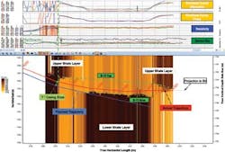
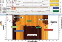
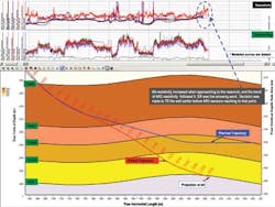
As the well trajectory came out of the 7-in. casing shoe at 4,228 m (13,871 ft) measured depth (MD), inclination was approximately 86° and was soon built to 88°. Once measurement sensors were out of the casing shoe, good reservoir was confirmed. Soon, the DTB measurements from PeriScope mapped a conductive boundary below the well path. Proactive geosteering decision was made to avoid exiting the reservoir by building the trajectory to 90.5°. Without the DTB mapper, the well would have exited prematurely into the shale below.
Production well ST-A-ST3 was drilled successfully with a total lateral section of 129 m (423 ft) of high resistivity interval, exceeding the initial objective of staying within the thin B15 sand for at least 100 m (328 ft). The well is producing more than 1,600 b/d with almost no water cut.
Production well ST-B
This was the first production well to be drilled into the Upper Oligocene C15 sandstone reservoir and targeted the crest of a complex structure with faulted closure. Because of uncertainties in the seismic interpretation of the top sand, reservoir depth, reservoir thickness, reservoir quality, and hydrocarbon content, the well was expected to become a pilot hole, in which case, the production well would be drilled as a side track.
To reduce the risk of requiring a separate side track in the thin (2 to 4-m, or 6.5 to 13-ft) target zone, the LWD program for the 8 ½-in. landing section was designed to land the well as close as possible below the top of the C15 reservoir to prevent losing sand thickness for the drainage section while evaluating reservoir quality at the same time.
To support this objective, the BHA included the geoVISION resistivity imaging-while-drilling service, which measures resistivity at the bit to provide the earliest possible indication of an approaching resistivity contrast—in this case the highly resistive C15 hydrocarbon-bearing sand—enabling proactive geostopping.
This technology was seen as the best solution because of the zero measurement offset from the bit. The other LWD measurements would be further behind the bit, resulting in significant sand penetration before the top of sand could be identified.
A change in resistivity of 20% is usually sufficient for induction or laterolog devices to confidently detect a bed. In addition to identifying bed boundaries, the LWD application can indicate whether the target sand has potential hydrocarbons in place. Real-time measurements of resistivity at the bit can also help to determine optimum casing placement and/or coring locations.
The imaging-while-drilling tool takes electrode resistivity measurements in wells being drilled with water-base (conductive) or oil-base (non-conductive) drilling fluids. It may be run in any of several configurations, providing up to five resistivity measurements for formation evaluation and wellbore positioning in a conductive mud environment. In resistive mud environments, the geoVISION service provides a single qualitative measurement of resistivity at the bit.
Laterog devices are usually used in conductive drilling fluids to allow the alternating current passing through the annulus into the formation and to close a loop. The bit resistivity measurement uses toroids insulated from the tool body to generate a measure of the current that passes through the mud into the formation. The monitor toroid above the transmitter measures the amount of current flowing on the tool collar, which is directly proportional to formation conductivity and is used to convert the measured current into resistivity.
Well ST-B was drilled with synthetic oil-base mud, which is non-conductive. Therefore, the ring and button sensors on the tool could not be used to measure formation resistivity. However, current does flow out the bit face that is in contact with the connate formation, and this allowed the bit resistivity measurement to be made. In this case, the lower monitor is used. Even though it is very close to the transmitter, it is not affected by a high current density because of the lack of current present in the mud. The current leaves the imaging-while-drilling tool at the bit, since this is in direct contact with the formation. The current is looped by returning at some touch point on the tool's stabilizer or BHA above. The upper monitor is used only because most of the current returns to the near-bit stabilizer mounted on the tool just above the monitor.
Acquiring high-quality at-the-bit resistivity measurements in oil-base mud requires good and consistent contact between the bit and the formation. Constant weight on bit and careful monitoring of the drilling parameters prevented the bit losing contact with the formation, helping to provide reliable resistivity-at-the-bit measurements to make critical decisions for geostopping and to land the well inside the target sand.
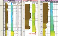
Top of reservoir was penetrated at 3,315 m MD (2,197 m TVD), 14 m TVD deeper than expected. The reservoir was confirmed by a bit resistivity measurement of 30 ohm/m and hydrocarbon shows in the cutting samples. The well was landed at 0.5 m TVD below the top of C15 reservoir with an inclination of 87.3°. The casing shoe was set at 3,323 m MD.
The 6-in. production hole was geosteered using the DTB mapper to maximize exposure in the thin sand. As in the previous well, thorough pre-job modeling was performed to understand the tool response in the target formation. The total lateral section was 135.6 m MD in open hole and 57m MD in the reservoir, producing around 1,200 b/d without any water cut and exceeding CLJOC's expectations. Through the use of advanced LWD technologies, the well was drilled without the need for a pilot hole and maximized in the target reservoir, improving the production rate.
Offshore Articles Archives
View Oil and Gas Articles on PennEnergy.com
