Alfonso Mora Rios
Aciel Olivares
Leonardo Aguilera
Rito Gaitan
PEMEX
Adrian Cristian
Sanchez Rodriguez
Schlumberger
The sedimentary basins of the Gulf of Mexico (GoM) exhibit a wide range of different geological characteristics, especially in the presence of complex salt bodies. Surface seismic surveys do not accurately image the borders and bases of salt domes. In addition, rapid lateral and vertical changes in acoustic velocity introduce uncertainties into the estimation of depth from seismic data.
In exploration areas, the lack of a priori information means that several uncertainties cannot be eliminated until at least one well has been drilled that provides reliable downhole information that can be integrated with the seismic data to calibrate depth models.
Well planning
The Well-1 was drilled through the flanks of, and then beneath, a salt dome in a deepwater area of the southeast region of the GoM. Analysis of a 3D seismic dataset indicated shallow drilling hazards in the area, which constrained the options for the well location at the surface. Other drilling challenges included the possible presence of a salt tongue at about 1,800 m (5,905 ft) related to the main salt body, and stresses related to salt tectonics.
A geomechanical study was performed to determine how stresses could affect wellbore stability in the section close to the salt flank. A rapid increase in pore pressure was suspected to exist in sediments beneath a fault plane at 2,200 m (7,217), so it was considered important to set the 16-in. casing just below the fault.
PEMEX decided to use the seismicVISION seismic-while-drilling service to deliver real-time check-shot and interval velocity measurements, plus data for look-ahead vertical seismic profile (VSP) processing.
Seismic-while-drilling
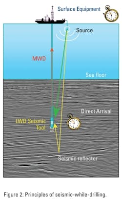
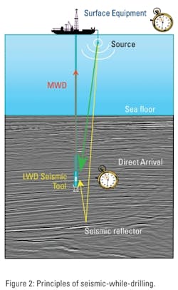
Seismic-while-drilling technology provides borehole seismic data while the well is being drilled – without disrupting operations. The seismic source is an airgun array deployed a few meters below the water. The data are recorded using three geophones oriented orthogonally in x, y, and z directions, plus two hydrophone pressure sensors usually transmitted to surface through mud-pulse telemetry.
The measurements enable accurate time-to-depth conversion of surface seismic data and provide critical indications of the structures of reflecting horizons ahead of the drill bit to support drilling and well construction decisions such as casing points and target interception. Real-time velocity measurements also can be used to update pore-pressure predictions from the surface seismic, helping to avoid drilling hazards.
Feasibility study
A study was performed to determine if the seismic-while-drilling technology could help with the drilling challenges of Well-1 and, if so, to design optimum data acquisition parameters. The study was based on a 3D model with interpreted horizons and velocities from the surface seismic – including for the main salt body – plus density values and the proposed well trajectory. The study focused on two key objectives: detecting salt ahead of the drill bit in the shallow (16-in.) section and measuring proximity to the main salt body in the deeper (13 3/8-in.) section.
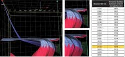
(Left) Salt proximity results (red dots) vs. interpretation. (Upper center) Salt flank from interpretation vs. salt proximity. (Lower center) Interpreted salt was moved to adjust with salt proximity results. (Right) Table showing the distances between salt flank and well position for each recorded statio
Two scenarios were modeled for the shallow section – one with clastic sediments and the other including a salt tongue associated to the salt dome. This latter scenario could present risks, as it would normally require changes in mud weight and also could require additional casing at the salt exit. The simulations assumed sensors along the whole 16-in. vertical section (1,500 – 2,200 m [4,921 – 5,905 ft]) and a zero offset VSP (i.e. having the energy source at the rig location). The study showed that seismic-while-drilling data could differentiate between the two possible geological scenarios. This difference will lead to higher amplitude reflections from salt/sediment interfaces than those between sediment layers.
Modeling of the deeper (13 3/8-in.) vertical section focused on optimizing the measurement of the distance between the well and the flank of the main salt body. A key objective was to determine the best location for the seismic source at the surface to deliver most energy to seismic-while-drilling sensors below the salt, taking into account ray bending caused by the complex geology. The study determined that the optimal location for the source was 2,700 m (8,858 ft) from the rig at an azimuth of 270°.
Acquiring VSP data
The BHA included a seismic logging-while-drilling (LWD) tool located 33 m (108 ft) from the drill bit. The source array of 1,200-cu-in. capacity was deployed from a service vessel. The (nominally) zero offset VSP data for the 16-in. section were acquired with the vessel stationed near the rig to avoid potential interference with drilling operations.
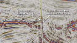
Seismic measurements were acquired at 17 levels between 1,503 and 1955 m (4,931 and 6,414 ft). The data were acquired in real time and transmitted on-site for quality control (QC) and additional processing. For each level, time-to-depth relationships based on check-shots were provided to the drilling and operations team members who used the information to update the drill bit position within the 3D seismic volume. After processing of the first five levels, a VSP corridor stack was prepared that provided information ahead of the drill bit. The VSP was updated constantly as new levels were acquired and integrated into the surface seismic data at the well location to check and confirm the drill bit position.
Analysis of amplitudes in the processed VSP data indicated the presence of clastic sediments rather than a salt tongue ahead of the bit, validating the initial interpretation of the geology and increasing confidence in drilling decisions. Drilling of the sandstone and shale interval between 1,800 m and 2,000 m (5,905 and 6,561 ft) subsequently confirmed the interpretation of the VSP results provided the seismic-while-drilling data.
The next challenge was to set the 16-in. casing at the correct position – just below the fault plane. The real-time check-shot data enabled the drill bit position to be mapped accurately within the seismic volume, and from measured velocities it was possible to estimate the distance from the current drill bit position to the fault plane. The start of the fault zone was estimated to be at 2,080 m (6,824 ft), and the sequence of upward-dipping sediments – suspected to have higher pore pressure – was predicted to start at 2,140 m (7,021 ft). Based on this information, when the bit reached 2,140 m, drilling was stopped and the 16-in. casing set to avoid any potential drilling problems in the event that abnormal pressures would be encountered below the fault.
Measuring salt proximity
A total of 18 levels were recorded between 2,175 and 2,658 m (7,136 and 8,720 ft). The seismic-while-drilling information was used by the processing team to estimate the distance between the well trajectory and the salt flank. Inversion of the seismic data to derive this distance was constrained by the 3D velocity model, updated with new information as it became available. Water velocity was assumed to be 1,500 m/s and salt velocity 4,500 m/s, based on previous measurements of salt bodies. Seismic velocity in sediments above the salt dome was determined from the check-shot survey acquired by the seismic-while-drilling tool in the previous section.
A real-time salt proximity solution was computed at every level. Estimations of the current horizontal distance between the seismic-while-drilling receivers and the salt flank were delivered to the G&G and drilling team every few hours. This distance was expected to be a minimum of 200 m (656 ft), but inversion of the real-time measurements indicated that the well was closer to the salt dome than expected. At its minimum, the horizontal distance was 163 m (534 ft) at 2,573 m (8,441 ft) depth; however, it was not considered necessary to change the well trajectory unless the distance was to fall below 150 m (492 ft), which it did not.
Seismic-while-drilling processing and interpretation support was provided continuously, 24/7, to the drilling operations team until the well reached 2,658 m (8,720 ft), at which depth it was determined that the critical zones had been drilled and the trajectory was moving away from salt dome, so it was no longer necessary to make the measurements.
Information acquired during drilling confirmed that the prestack depth migration (PSDM) results obtained from the 3D surface seismic dataset provided an accurate depth image of the salt dome. Interval velocities measured while drilling were used by the geomechanics team to recalibrate its models, especially for pore pressure prediction, bringing additional value to the information recorded.
Conclusions
Seismic-while-drilling technology helped to reduce drilling uncertainty in an area of complex geology related to the presence of salt bodies. Real-time VSP imaging provided information ahead of the drill bit that confirmed the well trajectory would pass through a clastic sediment sequence rather than a salt tongue as was considered possible by interpreters of the surface seismic data.
Real-time check-shot information made it possible to position the drill bit on the seismic section with great accuracy, reducing uncertainty related to depth conversion. This information also made it possible to optimize the position of the 16-in. casing to avoid potential problems related to increased pore pressure below a fault. Seismic-while-drilling data provided a real-time estimation of the distance between the well trajectory and the flank of a major salt body, providing confidence to keep the well within the planned minimum proximity to the salt.
The seismic-while-drilling results confirmed the accuracy of a model developed for the salt dome based on PSDM of 3D surface seismic data. Seismic velocities measured while drilling were used to recalibrate subsurface models, reducing uncertainty in pore pressure prediction.
Offshore Articles Archives
View Oil and Gas Articles on PennEnergy.com
