Case study offshore Malaysia
Azhar B Yusof
Petronas
Aqil Ahmed
T.K. Lim
Riasat Hussain
Schlumberger
Most wells are being drilled based on subsurface seismic information. Subsurface models based on seismic data are relatively accurate in terms of two-way acoustic travel time; however, converting seismic datasets to the depth domain still contain uncertainties potentially resulting in drilling risks.
Acoustic velocities for the depth conversion – derived from the seismic data itself – are inexact for the purpose, and drilling-target depths based on such conversions will have intrinsic errors. This depth uncertainty introduces increased levels of risk when targets are known to be over-pressured, where it is critical to stop and adjust drilling parameters before the target is reached.
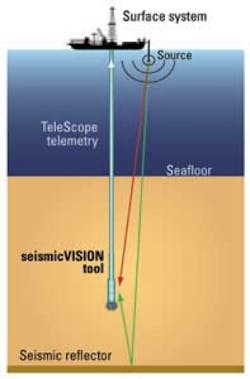
Schematic of the seismic-while-drilling LWD service.
Wireline-conveyed checkshot surveys have traditionally provided the velocity relationship between time and depth to enable more accurate conversion of seismic images; however, this information is not available until the borehole section has been drilled. The effectiveness and value of time/depth measurements is greatly enhanced when provided during drilling operations, when they can be used to support real-time drilling decisions.
The Schlumberger seismicVISION seismic-while-drilling logging-while-drilling (LWD) technology provides real-time checkshot surveys during the drilling phase. Target depths can now be updated before they are drilled, reducing uncertainty and risk through better-informed decisions, which can be particularly valuable in offshore developments.
Seismic-while-drilling
The key technology enabler for seismic-while-drilling is the use of a ruggedized ultra-high precision clock in the downhole tool that can maintain millisecond accuracy of global positioning system (GPS) time over periods of several days. This accuracy is essential, because while downhole in the bottomhole assembly (BHA), the seismic tool carrying the acoustic sensors has no direct physical access to times from the GPS satellites used to control the seismic source at the surface. The LWD tool is synchronized prior to running in hole and once again when the tool returns to surface, in order to measure the relative time drift while downhole.
The seismic source is the same as is used for a wireline vertical seismic profile (VSP) survey: a high-pressure airgun array controlled by a digital auto-tuning gun controller. For vertical wells, sources are usually deployed from the rig. For deviated wells, sources are often deployed from vessels located near to a vertical position above the LWD tool.
Seismic data are acquired during drillpipe connections. Connections are necessary breaks in the drilling process, so seismic operations are transparent in terms of rig time. Connections are also acoustically quiet, with no pumping or BHA movement. During a connection, typically 10 shots are fired, each with a 15-sec shot cycle time. It therefore requires 2.5 min per connection to acquire one checkshot level. The 10 individual waveforms are stacked together downhole, thus improving signal to noise ratio (S/N), and a windowed part – typically 500 ms long centered around the first arrival – is selected to be sent to surface.
Seismic waveform data are transmitted uphole by mudpulse telemetry when drilling and mud pumping resume. Depending on bandwidth, a 500 ms waveform typically takes twenty minutes to be sent uphole. Once at surface, the break time of the first arrival on the waveform is picked and processed, and the pre-drill velocity model is updated to produce revised target depth predictions.
Hydrophones, orthogonal geophones
In addition to providing real-time checkshot answer products, seismic-while-drilling has the benefit that it can be deployed from vertical to highly deviated wells without any concern. Hydrophone and geophone sensors in the seismic-while-drilling LWD tool are part of the drillstring. The geophone coupling with the formation is therefore achieved by gravity.
For instance, well deviation where the tool will be physically touching the formation. The geophones measure velocity in x, y, and z directions relative to tool orientation, and the quality of these measurements is dependent on the coupling between the geophones and the formation. For low angle, really shallow and large hole section where the toolstring is unlikely to touch the borehole, hydrophone is used to complement measurements from the three orthogonally mounted geophones. Hydrophones measure pressure transmitted from the formation via borehole fluids, so are independent of physical coupling. Utilizing hydrophone sensors ensures that a measurement always takes place and also provides a means to quality-control the geophone data.
Case study offshore Malaysia
Petronas used seismic-while-drilling LWD technology in an exploration field offshore Malaysia. A well drilled in the same area immediately prior to introducing the technology had encountered a kick due to the depth uncertainty of the over-pressured carbonate target. A particular challenge in this area is that the surface seismic data indicated a highly undulating pinnacle reef structure throughout the field.
Complex dipping structures such as this are generally harder to image accurately than simpler, flatter structures. Seismic-while-drilling was used to acquire real-time checkshots to improve the depth accuracy of the top of the over-pressured reservoir formation, in order to improve confidence in drilling decisions.
(Left image) Raw (unstacked) hydrophone memory data for a 10-shot checkshot at Well A. Note consistency between shots and strong first arrival (highlighted). (Right image) Real-time checkshot waveforms (example shown inset) for Well B indicated the actual target depth (red line) to be 150 m shallower than originally predicted (yellow line) from the surface seismic data.
Seismic-while-drilling technology was applied in two successive wells – Well A and Well B – located 50 km (31 mi) apart in the same field. Both wells were drilled using a semisubmersible rig at a cost of more than $500,000 per day. The wells were near-vertical, with deviations of less than 1° where seismic LWD was used on the 12.25-in. section.
Given the long wavelength nature of seismic waves – typically around 80 m – the seismic LWD tool is then placed at the upper end of the BHA privileging petrophysics measurement near the bit.
The source energy was provided by a 3 x 150 cu. in. airgun cluster, deployed from a crane on the rig, firing at a pressure of 2,000 psi for each shot. Eight to ten shots were fired for each checkshot level.
Stacked, windowed, hydrophone measurements from the seismic-while-drilling LWD tool were transmitted uphole in real-time. Hydrophone data was selected because this would ensure measurements irrespective of coupling and also from inside casing – assuming a good cement bond. The hydrophone belt circumscribes the tool, so sensor orientation is not an issue. Raw hydrophone data and the waveform measurements recorded by the three orthogonally mounted geophones were stored in memory for subsequent processing.
The real-time checkshot data were used to update the pre-drill velocity model as drilling progressed. Drilling interval for both wells was approximately 800 m (2,625 ft), and checkshots were acquired every second stand, reduced to every stand as the target was approached. For each well, the first two checkshots were acquired inside casing to establish a trend before drilling openhole.
Results
Seismic-while-drilling checkshot measurements were recorded for both wells with good S/N, as evidenced through post-drilling analysis of the raw data recorded in memory. The stacked, windowed, hydrophone waveforms transmitted to surface after each checkshot were used to update the velocity model while drilling. The recorded waveforms were also processed as vertical seismic profile (VSP) to provide an improved seismic image and accurate tie at the well.
For Well A, a total of 16 seismic-while-drilling checkshots were acquired. The real-time measurements indicated that the actual acoustic velocities were faster than those predicted by the pre-drill model. This meant that the actual target depth was deeper than originally expected by 87 m. As a result, casing was pushed and set deeper.
For Well B, 13 checkshots were acquired. Real time data indicated the actual velocities to be slower than the pre-drill model, indicating the target to be shallower than expected. The Well B target came in 150 m shallower than the original prognosis, and casing was set earlier accordingly. Drilling then proceeded with the correct mud weight.
Both wells were drilled to TD successfully and safely with no kicks. The fact that velocity/depth errors of significant magnitude – and in opposite directions – were found in wells just 50 km apart highlights the value of acquiring real-time seismic-while-drilling data.
Offshore Articles Archives
View Oil and Gas Articles on PennEnergy.com
