FLOATING PRODUCTION SYSTEMS Minimum surface equipment TLP hits $2/bbl capital cost for small field
Surface or shallow water access to wellheads, $1.50 operating cost,
and two years to production are attractive features
Dr. Pieter Wybro
SEA Engineering Associates
E. Donald Selle
MODEC (U.S.A.)
Milton Chaison
AmClyde Engineered Products
Deepwater tension leg platform (TLP) developments are generally associated with large capital and a long lead time to first oil, producing a high investment risk if not tied to a large hydrocarbon reservoir having minimal performance and size uncertainties. While TLPs are technically favored for deepwater development, they are not attractive to operators for smaller fields or uncertain reservoirs because of the large economic risks.
The industry is making an effort to find more economical means to produce in deep water. Basic objectives are to initiate production as quickly as possible, and at a minimum of capital and operating cost.
The question is, can TLP technology be used to fulfill these objectives, and still retain the positive features of TLPs, namely platform well completions? SEA Engineering Associates, Inc., in association with Mitsui Offshore Development Company (Modec) and AmClyde Engineered Products, Inc., have developed the minimum offshore surface equipment structure (Moses) tension leg platform to meet these objectives.
Moses is a small TLP that can be used in moderate to deep water and is suitable for small fields or as a building block for staged development of a large field. Advantages of Moses are the following:
- Economics: The turnkey capital cost for the installed Moses platform and facilities is less than $2/bbl for a 50 million bbl recoverable field. Operating costs of the platform, including well maintenance costs, are similar to typical Gulf of Mexico platforms which average about $1-1.50/bbl. The platform can be delivered in less than 2 years and can be provided to operators on a lease basis, much like a floating production storage and offtake (FPSO) system.
- Flexibility: Not all of the wells need to be pre-drilled since post-installation drilling can be performed using a semisubmersible drilling rig. Also, the platform can be relocated and reused in another location and water depth when the field is depleted, much like an FPSO.
- Well access: All wells can be platform supported, providing ease of well system maintenance and simple well systems.
- Efficient methods for platform weight management and payload reduction.
- Innovations for substructure, well systems, mooring and foundation systems.
- Installation methods utilizing a low cost spread and readily available installation equipment.
- Well workover equipment that is of standard design which enables the operator to use leased equipment only when needed.
These design and installation innovations produce a low cost system with good reliability and redundancy because they are based on methods and equipment that are proven for other applications with similar duty.
Design features
The first step in the design streamlining process is to reduce the payload which is achieved by the following:
- Reducing required riser tensions while still retaining platform completed wells, by virtue of the riser and well systems design.
- Downsizing the facilities to support only minimum facilities which can include first stage separation, well testing, and gas compression.
- Eliminating the platform drilling capability, but retaining all well completion and workover capability from the platform.
The main features of the base case platform design for 8 wells and 20,000 b/d production is summarized in Table 1. Designs for larger throughput are feasible as are platforms designed to support only wellheads, workover equipment, manifolds, and test separation facilities.
Mooring
For Moses' mooring system the traditionally high cost tendon end connectors have been replaced with a grouted connection at the top and a direct flange connection to the pile at the bottom.
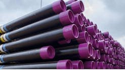
Titanium stress joints are used at the top and bottom in lieu of conventional elastomeric flexbearings. By virtue of the good hydrodynamic performance of the hull, the tendon body is standard 13-3/8 inch, 72 lb/ft L80 wellbore casing with premium threaded connectors.
Depending upon platform size, three or four tendons per corner are used, which results in good redundancy in the case of a failed tendon. A tendon tension monitoring system (TTMS) can be incorporated into the inside of the bracing elements. The tendons are each connected directly to a two stage (42-in. and 36-in.) drilled and grouted pile via a flange connection made up at the surface.
Template
The template is a lightweight structure that provides a locating means for the platform wells and the foundation piles, and is not designed to carry any in-place loadings.
The template can be designed to provide development plan flexibility by having sufficient spare slots and enable tieback of delineation wells or perform delineation drilling from the template. The wells are drilled from a semisubmersible through the template, utilizing standard marine drilling methods and equipment.
Risers, well systems
The risers are 9-5/8 in. casing tiebacks which are supported on the lower hull by passive tensioner devices. In traditional TLPs, the risers are supported by the deck. Also, the risers and tendons are not the same length, requiring long riser tensioner stroke which is also due to large dynamic loadings of the riser on the unsupported span through the splash zone.
In Moses, the tendons and risers are effectively the same length, reducing the demands on the tensioner system. The risers are supported on the hull at a depth below water of about 80 ft by passive tensioner elements, which have a carefully designed spring rate which is selected to minimize required riser tension and stroke.
The trees are simple diver interfaced land-type trees and can be either single or dual completion, controlled with direct hydraulics, and with straightforward provisions for gas lift and chemical injection. Wells are accessed by short risers deployed from the workover structure that has been positioned over the desired well slot.
Surface (normally dry) trees can also be provided, based on operator's preference, whereby the riser is tensioned and supported at the same place, and a riser extension is used to position the trees below the lower deck.
A prototype for the Moses TLP was installed and tested by the Japan Ocean Industries Association recently.
Hull
The hull is a monotower structure with a small central cylindrical column and a large diameter base which provides the majority of the buoyancy and supports the production risers. The hull is configured to provide sufficient buoyancy for in-place conditions and has adequate stability for the temporary installation phases.
It is configured to reduce extreme and fatigue loading on the tendons by design of the hull dimensions to reduce the vertical wave loads, and by lateral position of the tendons from center to reduce tendon loads from the wave-induced pitching and rolling moments induced by wind, waves, and currents.
A prototype of the hull was designed and built in Japan under the sponsorship of the Japan Ocean Industries Association and installed off the coast of Japan for one year. The experience gained from this platform, and the performance data that was measured has advanced the confidence of the Moses platform.
The hull is multi-compartmented for ballast and for damage considerations, both in-place and during the temporary phases. The central column is compartmentalized, and has a central shaft for access to the lower hull, which houses the pump room. The tendon support braces are either a tubular frame with dry interior, or can be a fabricated stiffened box beam structure. In the latter case, the interior structure can be made completely accessible for internal inspections.
Topsides
The facilities are located on three decks and consist of first stage separation, gas dehydration, compression for either pipeline export or re-injection, liquids pumping and well test. Chemical injection and gas lift can be readily incorporated.
The deck structural weight is small because of the reduced payload, the efficient design that does not structurally interact with the hull, and reduced deck loads from having no riser or drilling loads. This reduced deck weight lowers the vertical center of gravity of the platform and reduces the mass moment of inertia to improve overall system dynamic performance.
Fabrication, installation
Moses has been configured so that the platform components can be assembled in a relatively short time at most US Gulf of Mexico yards. Due to towout and installation stability requirements, the hull and deck are fabricated separately. Specialized installation vessels and equipment such as underwater pile hammers are not required for installation.
First, the template is installed by the semi-submerged drilling vessel (SSDV) used to drill the development wells. The template installation takes less than 4 days of rig time, after which the development drilling program can commence.
After well pre-drilling, the platform anchor piles and tendons are installed by the SSDV in two stages. The casings for all the piles are first run on the drillstring, jetted in to the required penetration, and the holes for the piles drilled.
Each pile and tendon is then deployed as an assembly, run down guidelines and stabbed into the installed casing. The casing has a J-slot connection at the top which is then temporarily engaged to the top of the pile, and the tendon buoyancy assembly is inflated so that the tendon is free-standing. When all tendons have been installed, the foundation piles are batch grouted.
The SSDV is then moved laterally on anchors, and control lines and assist tugs are used to maneuver and position the Moses hull over the pre-installed tendons. Pre-rigged tension lines are then lowered by small capacity winches on a temporary winch deck and connected to all the tendon tops.
The tensioner lines pass through temporary gripper units located on the top of the tendon connection sleeves which are all activated and the hull is then ballasted down over the top of the tendons. The grippers allow the hull to ratchet down on all the tension lines simultaneously, preventing upward movements, and provide temporary lock-off tension as the receptacles engage over the top of the tendons.
When the hull reaches the prescribed draft and horizontal trim, ballast is then pumped out to tension all the tendons to a storm safe load, and then the permanent tendon top connections are grouted. Tendon tensions are brought up to operating value by deballasting when the grout has sufficiently cured, and the temporary gripper and tensioning ropes are then removed.
A crane vessel is used to install the integrated deck structure and facilities, although alternate installation methods without a crane barge are currently being developed. The topsides package is loaded out, transported on a barge and then lifted onto the hull using conventional procedures. Prior to setting the topsides, the tendon tension is increased by deballasting.
Platform operations
Normal production operations are routine. The base case platform is designed as manned and provides quarters for up to 16 men. The normal crew complement consist of production personnel and a licensed barge engineer, and additional temporary quarters can be placed on the platform during workover activities. Also, if the platform is operated as a wellhead platform, it can be designed as unmanned.
All well intervention except drilling and sidetracking operations can be performed from the platform. A permanent, skiddable workover structure interfaced to the outside of the deck can be skidded over each well location and used to support the workover operations. Contractor-furnished workover equipment can be placed onto the top of the structure, which functions as a rig substructure.
Minor work-overs are performed using standard equipment. A high pressure steel tubing riser is deployed from the workover platform to the top of the tree and connected either by surface air divers or remotely. The work-over lubricator BOP assembly is attached to the top of the riser which permits normal wireline operations to be performed.
Major workovers and re-completions are performed much like on a fixed platform using leased equipment that can be either a hydraulic snubbing unit and associated equipment or a mast-type workover rig. Mud pumps and reserve mud pits are set onto the upper deck which has about 6500 sq ft of available laydown area. A pump boat alongside the platform is used during well completion for chemical flushing, etc., reducing the deckload and payload requirement substantially.
Temporary workover equipment such as mud pumps, mud pits, and generators can be positioned on the deck laydowns to reduce eccentric loadings, and thereby reduce ballast requirements. Tubulars are racked on the workover structure which then enables the use of conventional leased workover rigs, since there are no lateral dynamic loadings in the mast or support structure, and it can be laid down in a storm.
Post-installation drilling
Not all the wells need to be pre-drilled, even though the platform itself does not support a drilling system. There are several methods that can be used to perform post-installation drilling. The preferred method for deep water is to use temporary moorings (two or three) to pull the platform towards one side while a SSDV moors a safe distance away on the other side. Drilling is performed using the SSDV drilling systems, independent of Moses. Key to the feasibility of this method is sufficiently deep water and the wells located on the outside periphery of the platform. The design of the TLP holdback moorings, and the separation distance between vessels are carefully selected to produce a safe operation, even if an extremely rare failure of a mooring line occurs.
If the weather increases beyond the safe operating limits of about 17 ft significant wave height, operations are suspended and the SSDV moves on anchors a safe distance away from the TLP with its riser connected. In advance of a tropical storm, the riser is disconnected and the SSDV moves well away from the TLP.
Moses' low capital cost and short project cycle time combine to reduce the time to positive project cash flow. Moses also retains the major benefits of conventional TLPs (such as platform wells) which keep operating costs low. These two factors allow development of smaller deepwater fields, and can enhance the return on investment for larger fields.
Editor's Note: This technical paper was originally presented at the TLP Technology Symposium, held earlier this year and sponsored by the Texas Section of the Society of Naval Architects and Marine Engineers (SNAME).
References:
Wybro, P.G., Selle, D., Chaison, M., Development of Deepwater Fields using Moses Small TLP, TLP Technology Symposium of the Society of Naval Architects and Marine Engineers, Houston, February 1995.
Japan Ocean Industries Association (JOIA) under the Ministry of International Trade and Industry, Report of Investigation and Research Work on Ocean Petroleum Development Platforms, March 1994.
Kanetsuna, M. et al., Field Measurement Results on Dynamic Responses of One-Column Type TLP, The Society of Naval Architects of Japan, Vol 176, 1994.
Copyright 1995 Offshore. All Rights Reserved.
