PIPELINE TECHNOLOGY Remotely installed supports help remedy seabed pipeline spans
Brian C. Webb
BKW
Pipeline supports show ability to stabilize a pipeline in emergencies.
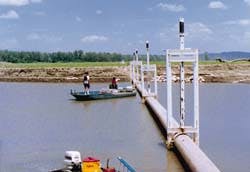
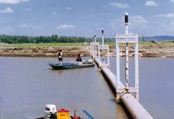
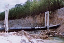
During a flood, long sections of pipelines were washed out, leaving unsupported spans. BKW pipe devices were deployed to support the pipelines.
- Pipe supports are lowered to brace a pipeline installed over a rock outcrop or left stranded as a result of a washout around the outcrop.
- A pipeline crossing is dealt with by deploying pipe supports.
Underwater pipe spans can occur during the installation of pipelines or anytime afterwards as a result of currents scouring the bottom. These spans can produce excessive pipe stresses, and if allowed to increase in length, can cause pipe failure. In addition, the spans are subject to currents that can create vortices, which will cause pipe vibrations and pipe failure due to fatigue.
During construction, pipe spans are usually created when the pipe is laid across a rock outcrop that protrudes above the bottom of the ocean or when the natural sag of the pipeline will not allow the pipe to remain in contact with the bottom for support. When this occurs in deep water, telescoping pipe supports can provide the necessary support.
The design of the support will consider pipe diameters, desired specific gravity of the pipeline, current velocities and direction, bottom conditions, and fishing trawler activity.
When the design is complete, the supports are installed using a surface vessel, installation tool, and a remotely operated vehicle (ROV).
The installation tool is equipped with the required hydraulic functions for installing the pipe support and expanding the legs. A lifting device located on the surface vessel is used to lower and raise the tool during pipe support installation. On the surface vessel, the tool is attached to the pipe support and lowered to the pipe span.
When the installation tool and pipe support are on location, the pipe support is attached to the pipe using the ROV. The ROV is equipped with a hydraulic power pack. The support legs are extended to the bottom to raise the pipe to the desired elevation to reduce pipe stress. The tool is then disconnected from the pipe support and raised to the surface vessel for reloading another pipe support. The installation procedure is then repeated until the pipe span has been stabilized.
The telescoping pipe supports have successfully demonstrated the ability to provide adequate pipe support during emergencies. The supports were used in various pipeline river crossings in Missouri and Texas during times of flooding. The selection of telescoping pipe supports was based on low cost, quick deployment, and a minimum of equipment required for installation.
River crossings
During the 1993 US floods on the Missouri River near St. Louis, several pipelines were effected by washouts. These pipelines were located on the flood plain, some as much as a mile from the river channel. Two of the pipelines were owned by Explorer Pipeline and Koch.
The two pipelines crossed a farm levee that just happened to blow out at the pipeline crossing and caused a washout 420 ft long and 85 ft deep. This created a 420-ft long span on both pipelines. Accessibility was limited to helicopters, because the flood plain was inundated with floor waters and the US Corps of Engineers' levee blocked boat traffic.
Several options were considered for supporting the pipe spans.
Each option would have to consider the length of span and the pipe stresses as a function of span length to air and water. Other considerations were the flood water current velocity, should heavy rains cause additional flooding, and the ability of a support system to raise the pipe span to reduce pipe stresses to acceptable limits.
Options considered included pipe clamp-equipped piles that could be driven into the bottom. This method could not be used because heavy equipment such as barges and cranes would be required and accessibility was limited to helicopters.
Cement bags were considered, but the cost and time required to airlift the cement bags was prohibitive. Five concrete bag supports would be required and the height of the support would be 65 ft with a base of 130 ft square using a one-to-one slope. In addition, air bags or some other means of lifting the pipe would be required to take the sag out of the pipe span prior to completing the cement bag supports. A means of attaching the pipe to the supports would be required because of the possibility of renewed flooding. This would cause a strong current that would wash the pipe off the supports.
The option selected was a telescoping pipe support developed by BKW, which included an installation system using a small barge. The barge, pipe supports, diving equipment and personnel were airlifted to the location and the supports installed. The telescoping pipe supports were a single leg design and the telescoping feature was designed to raise the pipe, thereby reducing the pipe stress.
The weight of the pipe filled with liquid in air was the basis of design. Calculations were made to determine pipe support spacing and the minimum allowable deflection.
Some minute stress would occur as a result of the single leg supports leaning away from the centerline of the pipeline.
The single leg support included a mud pad and cleat on the bottom of the support, and a pipe clamp and fill valve at the top. A buoy was attached to keep the pipe support in the vertical position when the helicopter dropped the pipe support on location. A work barge equipped with a hand winch was lowered on location by the helicopter.
The installation procedure included the placing of the pipe supports and work barge on location. The work barge would be tied to the pipeline at the point to be supported. A work boat would bring the pipe support buoy alongside the work barge and the pipe support connected to the winch on the work boat.
The pipe support buoy would be cut free and the pipe support clamped to the pipeline. A water pump on board the work barge would be used to expand the telescoping pipe support to the desired elevation. A range rod would be used to measure the elevation.
Adjustments could be made on the pipe supports at a latter date should span conditions change.
Explorer Pipeline also had a washout approximately 40 miles west of the earlier washout that caused two spans that were 180 ft each. Maximum depth of the bottom was 10 ft below the pipe.
However, this washout was connected to the river and when the river receded, the pipe in the washout would be exposed, thus creating a stress problem. A one-size-fits-all dual leg telescoping pipe support was installed at this location.
The installation included the use of the small barge and helicopter used on the first job. Post pads were used on these pipe supports because the legs were required to penetrate the bottom. This was to give support to the pipe in case the river current scoured the bottom to additional lengths.
The post pads were installed after legs penetrated to refusal to give additional support in case the legs settled. The pipe elevation was determined using a survey instrument, and when the flood water receded below the pipeline, the pipe elevation was adjusted.
Emergency deployment
During the 1994 San Jacinto river floods, the Explorer Pipeline washed out causing a 270-ft span. The one-size fits all supports left over from the Missouri washouts, and the work barge were shipped to Houston.
On October 23, 1994, the flood waters had receded to the point that the washout site and pipe could be examined using divers. Temporary cement bag supports were installed. A plan was established to provide a more stable support to the pipe.
The next day, the pipe supports were installed by helicopter in four hours and the pipeline system was sufficiently supported for service by the afternoon of October 24, 1994, only 36 hours after the flood waters went down.
In addition, an eight-inch pipeline was supported at the same washout location using single-leg telescoping supports. These pipe supports and an installation tower had to be fabricated and shipped from Tulsa, Oklahoma. Supports were installed on October 27, using two l4-ft boats and the installation tower. The tower legs straddled the pipe and was supported by the two boats.
Also during the Houston floods, Explorer Pipeline had a pipeline exposed in a drainage ditch. Two of the dual leg supports were installed as a precautionary measure in case additional rains would enlarge the ditch, and increase the span length. These supports were installed using a large crane. Divers were not required.
As a result of the four washouts experienced by Explorer Pipeline, the emergency response for washouts includes several dual-leg telescoping pipe supports that are stockpiled at a central location. These supports are modified for long-term storage and are ready for rapid deployment.
AUTHOR:
Brian C. Webb is a principal in BKW, a Tulsa-based engineering company.
Editor's Note: Parts of this article were presented at the International Workshop on Damage to Underwater Pipelines, sponsored by the US Department of Transportation and held earlier this year in New Orleans.
Copyright 1995 Offshore. All Rights Reserved.
