Practical challenges of manufacturing a 2.5-MW subsea motor
Brian Millward - Hayward Tyler Engineered Products
StatoilHydro specified a 2.5-MW electric motor that would survive without maintenance for at least five years for its Tyrihans field subsea seawater injection pumping station. That challenge is being met with advancements in fluid-filled electric motor technology.
The challenge to remove heat generated in motor windings and bearings was met with fluid-filled electric motors. The chosen fluid removes internal heat and the internal circulation system maintains the acceptable temperature in the winding wire and at the bearings for greater longevity while maintaining the thickness in the hydrodynamic bearings. With water being an abundant, low cost and environmentally friendly subsea cooling medium, it is the preferred choice for the fluid filled motor.
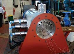
Hayward Tyler is building three 2.5 MW induction motors for Aker Kvaerner Subsea (Norway) to drive the Tyrihans subsea seawater injection pumps. The motor is a wet wound design and is filled with a hydraulic control fluid known as MPG/water (40/60 ratio, respectively), and incorporates a double acting tilting pad thrust bearing that carries the full thrust from the combined pump and motor. The motor is driven through an inverter and operates from 3,000 rpm to 4,000 rpm with a minimum continuous speed of 2,500 rpm.
The electrical motor is a 2 pole, 2500 kW, 3 phase, 6,600 V, 60Hz (3,600 rpm) induction motor designed as follows:
- Design lifetime -- 15 year (minimum)
- Time between intervention -- minimum 5 years
- Number of start/stops design value – 4,500
- Rated total thrust 26 kN acting downward (3,300 rpm, rated flow)
- Minimum total thrust 5 kN acting upward (4,000 rpm, duty flow, worn pump)
- Maximum total thrust 46 kN acting downward (standstill).
Mechanical design
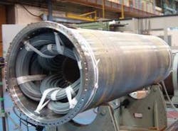
The design aim is to produce a motor of minimum overall length and weight. Stator, bearing housing, and rotor are mounted in a non-pressure retaining shell, separate from the motor case. This enables a full diameter opening at the DE only, which allows for a shorter motor. The separate stator shell design is standard for boiler circulating pump motors at 325 bar (32.5 MPa).
At start-up, the tilting pad thrust bearing operates with only boundary lubrication and does not achieve a fully hydrodynamic operation until it exceeds 200 rpm. During start-up from 0-200 rpm, the friction in the bearing is relatively high, then drops when a hydrodynamic film has been established. Built into the thrust disc is a centrifugal pump impeller that circulates the MPG/water mix around the motor to cool it. This impeller and thrust bearing absorbs power and consumes approx 205 kW at the max operating speed of 4,000 rpm (this figure includes all of the losses of the bearing).
There are two material options for the thrust bearings, either T2 thrust disc running against steel pads, or T3 pads running against a steel disc. The boundary lubrication friction coefficients for T2 and T3 differ. T3 is much lower, and therefore is preferred. The wear characteristics of T2 and T3 also differ during boundary lubrication conditions. Again, T3 is superior and thus preferred.
T3 has been used successfully by Hayward Tyler for tilting pad journal bearings, but this motor is the first to use T3 in a thrust bearing. The technical advantages against risks have been evaluated by Hayward Tyler, AKS, and Statoil. The conclusion was that the Tyrihans motor should be fitted with a T3 thrust bearing assembly, with a caveat that in parallel with the manufacture of the first Tyrihans motor, a set of verification tests should be conducted on a separate test rig to simulate the Tyrihans bearing configuration and operation, particularly during start-up and the boundary lubrication phase.
The motor is at some distance from the power supply. This location could cause voltage doubling in cases of fault that could damage the winding insulation. Therefore, although the motor is to operate at 6,600 V, its winding insulation is required to withstand 11,000 V.
The winding cable consists of 19 stranded copper wires of 1.2 mm each totaling about 6 mm in diameter (21.48 sq mm). The copper size accommodates the rated current with a current density below 12.5A/ sq mm.
A 0.25 mm thick layer of semiconducting material of surrounds the copper. This helps smooth the electrical field in the cable to reduce electrical stresses. The next layer is XLPE insulation 3 mm thick. This thickness insulates against 11 kV and ensures that the electric field (E) does not exceed 3.3 kV/mm at 1 1kV (design limit). The electric field is much lower at the normal operating condition of 6.6 kV.
An outside layer of nylon (PA) surrounds the cable. This layer is mechanical protection for the soft XLPE during the winding process, etc.
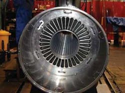
The motor has 36 stator slot and 28 rotor bars. This combination has been used on many of Hayward Tyler’s 2 pole motors. The thickness of the stator teeth and depth of the back iron in the stator core, in addition to the rotor iron core, were carefully selected to ensure adequate magnetic flux density but not to cause saturation. This also covers the range of all specified operating points.
The stator cable winding is concentric with 13 conductors per slot. It is connected in two parallel star circuits. This results in two internal star joints and three 2-1 internal joints between each of the two ends of each phase and the internal lead cable attached to the boundary interface gland joint. These internal joints are used by Hayward Tyler on all motors and are manufactured in house in XLPE. They cover a range of voltages and currents. There is a large stator/rotor gap in order to reduce heat from the various sources of losses. Most of the loss is from friction. The gap radial width was chosen following many iterative processes between the electrical and mechanical designs.
Motor performance
Motor performance is illustrated in motor performance curves and current and torque versus speed curves.
Motor modeling software addresses the requirements of motor design for Hayward Tyler. It was written many years ago and went through intensive checking against measured results conducted during the test on numerous manufactured motors.
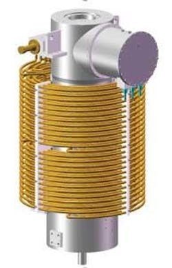
The system is liquid filled and any volume change due to pressure and temperature variations are taken care of by a Pressure and Volume Regulator (PVR). Forced circulation is provided by a centrifugal pump in the motor non-drive end (NDE). The pump impeller is fixed directly to the motor rotor shaft. The heat exchanger consists of several coils arranged in parallel and externally exposed to seawater. The motor internal circulation provides the cooling of the stator windings and rotor in addition to cooling and lubrication of the bearings and mechanical seal. A temperature sensor is set inside the inlet to the cooling coils.
The circulation pump is in the motor non-drive end housed within the thrust bearing. It is a radial diffuser centrifugal pump with an anti-vortex baffle. The initial motor design included a 3-stage impeller design. However, the revised design is a single-stage pump which has a positive effect on the rotodynamics, reduced rotor length, and is simpler.
Design duty – 100 liters/min @ 97 m, 3,300 rpm
Rated duty – 1,000 liters/min @ 120 m, 3,300 rpm
The rated duty provides a margin for reduced pump performance with wear.
Impeller dimensions are as follows:
- Outer diameter – 350 mm
- Number of vanes – 3
- Eye diameter – 135 mm
- Vane outlet angle – 16°
- Hub diameter – 104 mm
- Outlet width – 8.5 mm
Diffuser dimensions are:
- Outer diameter – 420 mm
- Number of vanes – 5
- Inner diameter – 357 mm
Internal flow
Motor coolant heats as it is pumped through the stator/rotor/starter gap (airgap) bearings and then cooled as it passes through the cooling coils. Controlled leakage through wear rings cools the thrust disc and thrust bearing pads. Of the total 530.2 kW heat rejected, 86% is from frictional heating and internal pumping loss, the remainder from electrical losses. Cooling coils account for 100% of the heat rejected since only a very small amount is lost via the motor case. The circulation pump design flowrate of 1,000 l/min (15,850 gal/hr) is required to limit coolant temperature rise in the motor/stator gap to a maximum of 65° C (149° F). Coolant emerging from the gap is in immediate contact with the electrical winding end turn insulation and a limit on coolant temperature of 70° C (158° F) is needed to give a 15-year winding life. With one circulating pump impeller, a minimum of six cooling coils in parallel are required to match cooling area with acceptable head loss.
- Motor speed, 3,300 rpm 3,804 rpm
- Design flowrate through stator windings, 605 l/min 660 l/min
- Design flowrate through rotor/stator gap, 295 l/min 340 l/min
- Total design flowrate through motor, 900 l/min 1,000 l/min
- Design flowrate through one coil, 150 l/min 167 l/min
- Total design flowrate through six coils, 900 l/min 100 l/min
Flow through the stator is restricted by orifices so as to force sufficient flow through the narrow rotor/stator gap to cool the rotor. The rotor/stator gap size has been maximized at 4 mm (radial) to minimize the head drop through the motor internals.
Materials, fouling, marine growth
To least greatly reduce fouling and marine growth, the electric motor pressure vessel has been fabricated in 25°C CR DUPLEX and all external surfaces painted to Norsok System 7. This is in addition to the cathodic protection system for the pump module. The external steel surface temperature is typically 30-40°C. The electric motor’s internal parts are fabricated in standard submersible motor materials. The internal surfaces will only be exposed to the freshwater/glycol mixture. The glycol contains a corrosion inhibitor. The cooling coil is fabricated in 22% Cr DUPLEX. For optimal heat transfer properties, no surface is painted. The external surfaces exposed to seawater are protected by the pump module cathodic protection system. The external steel surface temperature is typically 25° C (77° F). The internal surfaces is exposed only to the freshwater/glycol mixture.
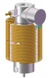
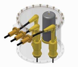
The heat exchanger consists of six parallel coils arranged external to the motor pressure casing as indicated in the sketch below. The external surface of the coils will be exposed to the surrounding seawater and cooled by natural convection. The internal coolant is freshwater /glycol mixture or Castrol Transaqua EA3. Fabrication: The pipe is butt welded from 6 m (20 ft) lengths and the coil shaping is done by cold forming.
Junction box
A key challenge for subsea motor manufacturers is to manage the high voltage power cable entry from the ambient seawater into the motor housing. The motor is housed in a pressure casing suitable for an over-pressure from within, defined by the pump operating conditions. This over-pressure can be in the region of 350 bar (35 MPa). In simple terms, the electrical power connectors enter the terminal box and connect to the motor terminals. The terminal box typically is on the seawater side of the motor pressure boundary and has to be in a suitable medium for electrical protection.
Where possible, proven technology is used to minimize the risk. A terminal box filled with transformer oil is an excellent medium for HV electrical connections. However, an extra dimension should be considered for subsea terminal boxes: What if the terminal box seal fails and seawater gets in? In this case, the actual connection of the copper cable end and the copper terminal stalk needs to be electrically insulated. To achieve this the insulation material (typically XLPE) on the terminal stalk and cable have to be bonded.
The operating temperature range brings in the complexity of thermal dimensional change. In the passive mode the motor is at the ambient seawater temperature – approximately 4° C (39° F). The design temperature for the terminal box, taking into account the electrical heating effect, the motor internal operating temperature, etc., and a suitable design margin, can be in the order of 60° C (140° F). The copper terminal stalk will expand away from the anchor point at the motor case pressure boundary, and the connector will grow from the terminal box sidewall. The challenge then is to design the insulation around the connection to accommodate this thermal cycling from the “cold” standby to “hot” operation.
Penetrator
The major design hurdle is the electrical penetrator. This is the terminal stalk that crosses the pressure boundary to deliver the power to the motor windings. It has to accommodate three major design parameters: electrical insulation, differential pressure, and thermal cycling.
Of these parameters, thermal cycling is the most easily addressed – anchor it at the pressure boundary. However, the mix of materials involved in providing the physical strength, the electrical insulation, and the copper itself turns this into the most complex challenge.
The amounts of material required for the mechanical strength dictates the physical dimensions and, in turn, results in an inherently highly electrically insulated penetrator. Extensive qualification testing is required to prove this is the case, but, as suggested above, the complexity of the different thermal properties of the materials used is a challenge.
