Finding optimal balance in rotary steerable systems
Steve Jones, Junichi Sugiura - PathFinder
Steve Barton - ReedHycalog
The selection of optimum gauge geometry for a rotary steerable system (RSS) varies considerably and depends on the RSS driving mechanism, application, and rock type. Since each RSS is different, the optimal drill-bit design must be customized for each system. Systematic testing is required to evaluate the dogleg and drillabililty of rotary steerable systems.
Directional drilling revolution
The first commercial RSS revolutionized directional drilling in the 1990s. The technology has made improvements in reliability and is now a standard drilling tool, with both push-the-bit and point-the-bit RSS applied in directional and vertical wells worldwide. Their use is not limited to high-cost offshore markets but is becoming more common in lower-cost land markets.
The advancement of RSS drilling goes hand in hand with the use of polycrystalline diamond compact (PDC) bits. Continual development of advanced modeling software and cutters with significantly increased abrasion resistance have led to PDC designs that can drill faster, further, and with a high degree of stability.
In directional applications, drill bit stability, and steerability are critical to performance. Without a smooth torque response or a laterally stable design, neither the desired rate of penetration (ROP) nor durability to drill the required interval is achieved. It is also important to match the side-cutting capability of the cutting structure and gauge geometry to the operating mechanism of the specific tool and the directional objectives. These factors affect borehole quality, which has a direct impact on the directional control of the RSS. Maintaining wellbore quality, particularly borehole gauge, is crucial for obtaining predictable directional response in both push- and point-the-bit systems. Also, with any RSS, directional control and borehole quality is linked directly to how quickly and precisely the internal control system operates.
Rotary steerable systems
The principle and drive mechanism of the commercial RSS have diversified over the years, with evolution in both push and point tools. The steering unit of the tool has evolved uniquely to be run in both point-the-bit and push-the-bit configurations. It consists of three hydraulically actuated pads for directional control, which also act as an anti-rotation device, to hold the steering unit stationary while drilling ahead. All three pads make full contact with the formation, and steering is accomplished by offsetting the steering unit in the desired direction. The RSS controls the dogleg severity (DLS) by varying the amount of offset that the steering unit creates from the center-line of the hole and the pads are constantly adjusted to achieve the target settings. This continuous adjustment to maintain orientation of the steering unit allows the system to drill a constant curve.
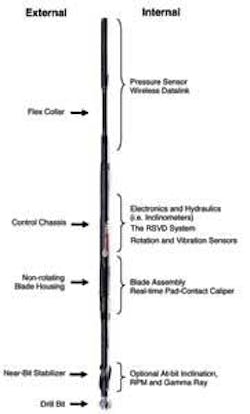
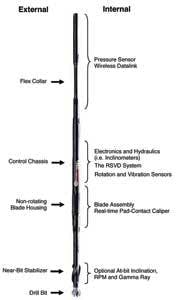
A typical 12 ¼-in. hole size PathMaker RSS in a point-the-bit configuration.
In push mode, the steering unit pushes the bit sideways in the desired direction, whereas in point mode, a full-gauge near-bit stabilizer is used as the fulcrum, allowing the bit to tilt in the required direction. There are advantages to both systems, depending upon the application. Typically the system runs in push-the-bit mode if excessive hole wash-out is expected or if higher degree doglegs are required. The former relates to the fact that the pad extension is considerably larger than that of conventional push tools and thus can maintain borehole contact in enlarged holes.
Tuning drill bit design
There are four fundamental characteristics of the fixed-cutter bit: durability, steerability, stability, and aggressivity. Drill bit designs need to be tuned in terms of bit profile, cutting structure, and gauge design to optimize performance for a given BHA, formation, interval, mud type, and directional requirement. One key for a rotary steerable assembly is the operating mode of the specific tool itself; an in-depth knowledge of the tool and field performance enables both bit cutting structure and gauge geometry to be matched with a specific RSS drive mechanism.
To determine optimal gauge geometry for the tool, a series of systematic tests was conducted with emphasis on the affect of bit gauge design on stability and steerability. The same primary cutting structure was used so that any variance in recorded stability and steerability would be directly related to the difference in gauge geometry used during testing. This testing was done in both push and point modes, not only identifying the optimal gauge geometry for each mode, but also allowing a true and accurate comparison between push and point mode using the same steering unit and bit design. The following four gauge geometries were tested:
- 1. Active gauge: This arrangement increases the lateral cutting ability of the bit design using exposed, full round cutters on the leading edge of the gauge pad
- 2. Dual action gauge (DAG): This gauge geometry incorporates a full diameter gauge pad with a PDC cutter selectively placed in a recess at the back angle of the gauge pad
- 3. SteeringWheel gauge: This gauge design features a continuous ring at the gauge diameter rather than discrete pads as in conventional bits. SteeringWheel bits were designed to improve directional response by improving lateral stability of the bit to reduce the propensity of the bit to whirl. By minimizing lateral vibration, the ring bit reduces torque fluctuations that can occur due to bit whirl. The majority of ring gauge designs used commercially feature partial ring geometry, which was applied within this test program
- 4. SmoothSteer gauge: The gauge pad of the drill bit is tapered at an angle that matches the tilt imposed by the RSS. The specific geometry of the proprietary tapered gauge avoids the frictional resistance produced in directional drilling, thus lowering torque and instability.
Systematic testing
Confidential drilling rig test facilities were used for the controlled RSS directional test program. These included the GTI Catoosa Test Facility near Tulsa, Oklahoma, and the Rocky Mountain Oilfield Test Center (RMOTC) near Casper, Wyoming. Both facilities provided adequate geological variations and rig/pump capabilities for the tests in 8 ½-in. (22-cm) and 12 ¼-in. (31-cm) hole sizes. With no directional constraints at either facility, each offered a perfect test ground for controlled RSS testing.
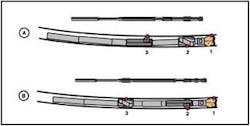
The point-the-bit (A) and push-the-bit (B) configuration tests indicated a small difference in the average build rate, which was 10°/100 ft in point-the-bit mode with 98% deflection, compared to 11.4°/100 ft in push-the-bit mode with 88% setting.
Throughout 2006 and 2007, the RSS in both push and point modes was tested with different drill-bits. An experimental 6 ¾-in. (17-cm) push-the-bit tool was designed exclusively for this systematic testing. The main objective of the control test was to establish the maximum dogleg using various bit gauge configurations and at the same time evaluate the system for stability, steerability, and borehole quality. Real-time and memory data was used to evaluate tool performance, and was recorded at one second intervals, allowing the steering control system to be evaluated between runs. This analysis was used to understand whether the geometry and drill-bit changes influenced the internal control system.
Push mode
Stability versus steerability was tested in push mode: All four gauge designs were tested on the 6 ¾-in. push tool in 8 ½-in. hole. With an 88% deflection setting, the active gauge design delivered nearly double the build rates (9.9°/100 ft [30 m]) compared to other designs tested. The active gauge bit was then run on the tool but with reduced spacing from the steering unit to the third touch point stabilizer (short push assembly). This 1.5-ft (0.5-m) reduction increased the build rate to 11.4°/100 ft, while maintaining a very stable assembly and encountering no drillabililty problems. Both short and long push assemblies were then tested with a 7-in. (18-cm) spacing increase between the steering unit and the bit. This extra spacing dramatically affected reducing build rate by approximately 4°-5°/100 ft.
Stability also was evaluated after each test. The memory data was retrieved and the near-bit vibration data was used to analyze bit stability. Test results revealed that the active gauge bit provided the highest DLS with the lowest lateral, axial, and torsional vibration at the RSS. This is because it efficiently removes rock when side force is applied, thus giving smoother drilling. Testing with 12 ¼-in. bits on the 8-in. tools revealed similar trends between steerability and gauge design.
Point versus push
The different gauge designs had a less dramatic variance in steerability when in point mode, with the SteeringWheel gauge marginally providing the highest build rates. The key point is in the comparison between push versus. point mode using the same primary cutting structure design of the bits. From analysis of the 6 ¾-in. (17-cm) assemblies, both push and point BHAs exhibited similar ROPs, good lateral, torsional, and axial stability, and borehole quality (consistent gauged borehole). There were no signs of borehole ledging or spiraling with either configuration. The only notable difference between the two is the average build rate, which was 10°/100 ft in point-the-bit mode with 98% deflection, compared to 11.4°/100 ft in push-the-bit mode with 88% setting. This was also evident in the comparison between the 8-in. push and point BHAs: Using a 12 ¼-in. bit with SmoothSteer gauge, an average build rate of 5.4°/100 ft was established in push mode (91% offset), compared to 4°/100’ average build rate in point mode.
Optimizing geometry
The results from several years of cooperative testing are:
- Active gauge produced the highest build rates in the push mode testing with both tool sizes
- The active gauge testing (push mode) produced the lowest levels of vibration due to its increased lateral cutting efficiency to the side force applied by the tool
- The SmoothSteer (tapered) gauge lowered the recorded stick-slip due to less friction and drag, compared to conventional parallel gauge geometry
- Reducing the spacing from the steering unit to stabilizer did increase the maximum build rate in push mode
- Increasing spacing between the steering unit and bit in push mode led to a drastic decrease in build rate
- Push mode delivered higher dogleg capability than point mode with both size tools
- The gauge geometry had limited effect on steerability in point mode with both tool sizes
- Matching the appropriate drill bit and RSS for the specific application results in optimized drillabililty, stability, steerability, and borehole quality.
