New design spar-like hulls show platform stability advantage
Gene Kliewer, Technology Editor
The problem of setting topsides onto jackets in sea conditions with 12-ft (3.7-m) swells has led to a new design to configure drilling and production facilities for water depths of 1,000 m (3,281 ft) or more.
The system
In one of its current applications, this new system is targeted for a 13,500-ton (12,247-metric-ton) displacement minimal well control platform in the Gulf of Mexico with four spar-like hulls supporting a typical open truss deck 120 ft (36.5 m) on a side. The central well bay provides steel catenary riser (SCR) and umbilical hang-off locations. The variable topsides equipment load - deck equipment, risers, and umbilicals - is 1,250 tons (1,134 metric tons). The required steel weight to support this payload is 2,800 tons (2,540 metric tons).
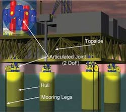
This system, called the VersaBuoy, reacts to applied environmental loads in a different manner than any other hull configuration. Its unique articulating connection between the top of each of the four hulls and the deck allows each individual hull to pitch and to roll independently from the topside, resulting in a significantly reduced pitch/roll motion of the topside under the applied environmental loads.
Rendering illustrates the attachments of the articulating joints to the bottom of the platform.
“The question is how to distribute the wave energy,” says Alaa Mansour, manager, naval architecture, VersaMarine Engineering Llc. “You want to have less energy from the wave transferring to the topside. The four small spar-like hulls respond to the wave action mainly like a pendulum with its rotation center at the keel of each hull. You are going to see some roll/pitch rotation angle in each individual hull, but the topside remains almost horizontal. The topside rotation is mainly dominated by the relative heave motion between the hulls, in other words, when the four hulls heave out of phase.
“Going out of phase depends upon the center-to-center hull spacing relative to the wave length,” Mansour says. For long waves, which are the wave components with high energy, the four hulls heave together. For short waves, the hulls could heave out of phase but there is not a large amount of energy. “For up to seven-second wave components, you see some out of phase heave motion. After that, the spar-like hulls heave together,” Mansour explains.
For this application, the articulating joint must transmit an axial thrust of between 1,000 and 2,500 tons (907-2,268 metric tons) and have a ±20° range of motion. The design puts the joint out of the splash zone at 55-60 ft (16.75 to 18.25 m) above sea level. As a safeguard, the joint has a redundant outer joint that allows the primary connection to be removed and replaced if needed while continuing normal operations.
“The only way to beat that swell is with a deep draft hull like the spar technology,” says Jon Khachaturian, president of VersaBar. “You have a long column that produces a heave natural period that is much longer than the swell period, so the swell motion, the up and down heave, is much less.”
Mooring is by either conventional catenary lines or a taut-leg system attached to fairleads on each hull. Each hull is sized and ballasted to be stable and to require no other constraint.
“You moor VersaBuoy just like a spar,” says Khachaturian. “The spar-like hulls are a little less loaded because they expose less area to the current loading.”
The VersaBuoy hull is subdivided as follows:
- A temporary ballast tank in the top section is used for hull deballasting during topsides installation. The topsides are installed via float-off. The temporary water ballast is installed quayside (as is the solid ballast) prior to a wet tow to the installation location. The temporary ballast is removed using compressed air from the deck. There are no internal hull mechanicals for this application.
- A center hard tank section is never flooded
- A soft tank compartment in the main hull legs, plus additional soft tanks at the base of the hull which provide additional buoyancy for the wet tow. At location, they are flooded to upend the hull
- A solid ballast section at the base of the hull in the main legs is installed in the hull at the quayside in the conventional manner.
Each hull has a structural weight of approximately 700 tons (635 metric tons) and uses 1,000 tons (907 metric tons) of solid ballast. The primary hull members for this system are made from 96-in. (244-cm) diameter rolled pipe with some internal ring stiffening.
Model testing, verification
Following multi-body analyses and simulations performed by VersaMarine Engineering, Llc., a six-week model test program was performed at the Offshore Model Basin (OMB) in Escondido, California. Model testing was performed at a scale of 1:53.
Four basic configurations were tested for GoM environmental conditions including 10-year winter storm, 100-year hurricane, and 1,000-year hurricane (Hs = 62 ft, or 19 m), as well as loop current conditions.
The configurations tested were based on a standard VersaBuoy module with the following characteristics:
- Two-level topsides each level 250 ft x 250 ft (76 m x 76 m) with a variable deck payload of 3,200 tons (2,903 metric tons)
- The deck is supported by four “jacket” hulls on 125-ft (7.6-m) centers
- Each jacket hull has a total length 457 ft (139 m), a design draft of 398 ft (121 m) consisting of 1,300 tons (1,179 metric tons) of hull steel and 2,400 tons (2,177 metric tons) of solid ballast. Each hull is fabricated from four 148-in (3.8-m) diameter tubular members on 27-ft (8.2-m) centers running the full length of the hull, with crosstie members every 90 ft (27.5 m). Two of the cross ties supports a conventional heave plate
- Eight-leg catenary mooring system (two legs per each of four hulls) modeled using OMB’s SMART system.
The modal analysis of a single module showed a deck heave period of 27 seconds and a deck pitch/roll period of 34 seconds.
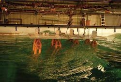
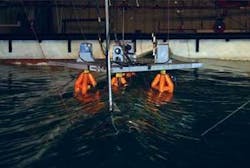
A single module in the wave basin during storm wave conditions.
The model testing program considered a single module, two modules combined to form a single 250 ft × 500 ft (76 m × 152 m) module, and four modules combined to form a single 500 ft × 500 ft (152 m × 152 m) module.
Three-hour extreme responses measured during model testing compare favorably with other offshore floating development systems. An additional benefit is the low drag loads for the selected jacket hull, which results in mooring loads of 30% to 40% less than those for other classes of system for the same displacement. Finally, wave run-up seen on columns and hulls for other systems (reducing local air gap) was not seen for the VersaBuoy.
“One advantage of this jacket hull configuration is that it forms a transparent structure,” says Mansour. “If you have a massive, bulky structure, huge waves get trapped in the well-bay area, and you have an air-gap problem. If you have a transparent structure like VersaBuoy, with small components, the wave will pass through. This helps reduce the minimum deck clearance requirement.”
“The motion response of VersaBuoy is mainly second order, which basically is a slow motion. This has significant advantage to the fatigue design.”
Minimal applications
Deepwater developments typically challenge floating systems to scale up for increasing payloads, riser counts, and drilling capabilities. There are exceptions where minimal solutions have been required. The VersaBuoy system shows excellent scale-down capabilities, illustrated by the 1,250-ton (1,134-metric-ton) payload system with a total hull structural steel weight (for all four hulls) of 2,800 tons (2,540 metric tons). Multiple body motions analysis also shows the extreme wave response of this small system to be very close to that reported for the model test results for the larger unit. This allows SCRs and umbilicals to be supported directly from the topsides.
“The topside weight limit is based on the size of the spar-like hulls,” says Khachaturian. “It scales up very well. We are working hard at making it small. A small facility in offshore deepwater has a lot of potential uses, such as minimal fields of 30-40 MMbbl reserves.”
The minimal wellhead control platform (MWCP) model for single or multiple wells tied back to local deepwater infrastructure calls for the facility to be located over the wells supporting a control and chemical injection umbilical and pigging riser.
The MWCP supports an autonomous control system that can control well functions, as well as redundant communication lines (microwave and satellite) back to the host. The default operating mode is with control from the onboard system.
The system offers cost and development schedule advantages. First, it features a shorter control umbilical at a length of 2-3 mi (3.2-4.8 km) from the MWCP instead of 20-30 mi (32-48 km) from the host. Second, there is a possible reduction of a pipeline leg and riser from the host. Last, there is less added payload on the host because chemical injection and control equipment is located on the MWCP.
The VersaBuoy system evolved from a study of the installation of single-piece 20,000-ton (18,144-metric-ton) topsides onto spar hulls offshore West Africa using the Versatruss deck installation system. Versatruss lifted booms are supported on the centerline of standard deck transport barges with pin supports that allow the barges to roll relative to the booms and hence the deck (one degree of freedom decoupled).
The motions of the topsides supported by the Versatruss system during the various phases of the operation were evaluated during the installation study. An optimization cycle considered the replacement of the standard deck transport barges supporting the Versatruss booms with four small cylindrical spar-type buoys, each supporting a single boom set, with the objective of further reducing deck motions during installation. For this configuration to work, it was necessary to introduce an additional release between the spar hull and buoy to decouple the hull pitch and roll motions from the booms using an articulating connection.
