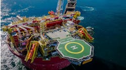
A few drilling difficulties in 10,000 ft depths
What is the difference between drilling a well in 7,000 ft water depths, which has already been done, and drilling one in 10,000 ft depths, which is being considered by at least two operators and a number of drilling contractors?
Early discussions on two such projects indicate that most equipment used on a 7,000 ft well can be extended to 10,000 ft depths, with only a commensurate increase in loading expected. The broadest hurdle appears to be economic, due simply to increased rig time on the hole, especially if the target formations are far below the seabed. Some of the interesting challenges and requirements center around the following:
- Surface equipment: In order to reduce long tripping periods and prevent swabbing, a top drive unit will be necessary. Higher capacity mud pumps will be needed to create sufficient fluid velocity in the riser to lift cuttings. High tension levels in the drillstring will necessitate the use of the best quality drillpipe.
- Drilling time: Drilling and under-reaming on the same trip, optional on strings in shallower water, is a must in very deep water. Separate trips for each function aren't economic.
- Drilling fluids: Because of exposure to low seawater temperatures through two miles of riser, drilling fluids and cement slurries become viscous. Thin polymer fluids are necessary, accompanied by substantial solids and sand removal and standby dilution. Salt saturation is recommended. A riser liner may be necessary to increase fluid flow velocity.
- Riser safety: Risers used in 5,000-7,000 ft depths can be extended for 10,000 ft depths, however the surface equipment must be able to handle additional riser loads in the event of can flooding or drive-off. There is also a concern that opposed shallow and deep currents could severely contort the riser. Careful control of riser top tension and buoyancy will be needed.
- Wellhead integrity: Bending stresses on the ball joint, wellhead, and conductor could surpass 200 ton-meters, meaning that wellhead and conductor top joints would have to be stiffened with extra casing and cement to cope with the potential for high lateral and tension forces.
- Geotechnical: As in shallower water, the likely scenario is for a highly unconsolidated seabed and aquifer flow zones to at least 1,000 ft below the seabed. A surface casing string within the conductor may be necessary to route water and sand flow to the seabed rather than allowing it to push up behind the conductor. In addition, shallow sediments will not support cement slurries. Once casing is set, numerous leak-off tests will be necessary. High pressure housings should be locked high in the conductor.
- Guidelineless operations: In very deep water, there is a high probability that guidelines used to lower wellhead components or ROV umbilicals will tangle around the riser. Drillers will have to minimize use of both, and provide sufficient standoff for ROV surface support.
- Flow testing: Associated gas and water coming from deep high temperature formations routed into a riser exposed to two miles of low seawater temperatures can form hydrates and paraffins quickly, blocking flows or skewing test results. Analysis of prospective production will have to take this possibility into account.
Top drive safety, reliability concern of UK's HSE
The safety and reliability of many top drive systems has been called into question, a matter of poor design in some cases, but more often improper installation, operation, and maintenance by drilling crews. This was the conclusion of the UK's Health and Safety Executive, Offshore Supplies Office, and Marine Technology Directorate.
The three agencies have pointed out that top drive systems appear to be less reliable than conventional rig drives. However, in defense of the systems, the agencies cited the harsh operating conditions in which the units are generally deployed. The HSE advisory cited the following:
- 1. Explosion protection systems on electric top drives are inadequate, both for closed loop and open loop cooling of electric motors. The demand to boost motor output creates problems in cooling protection.
2. Not all operators follow the manufacturers' recommendations properly with regard to installation and maintenance of the drop drive units, creating reliability problems later.
3. Boosting output from the drive motors is also creating cooling and system reliability problems for some units, and an assessment should be undertaken to evaluate the merits of power boosting.
Needed: fracture mapping service
The difficulty in determining the efficiency of hydraulic well fracturing methods, subsequent well treatment, and the overall economics of fracturing is obvious - uncertainty about the geometry and depth of the fractures and inability to image the fractures.
The Gas Research Institute and Sandia National Laboratories have outlined a methodology of fracture imaging and the development of a prototype service to provide that information to production engineers. No such service exists at present, the two point out, and the methodology is very thin.
Recently, the GRI developed a software program that predicts fracture geometry based on rock and reservoir properties that control fracturing. Tiltmeters can provide some information at shallow depths. Vertical seismic profiling can provide the detail to image the fractures, but shooting the wells and subsequent development of the seismic data requires weeks of time and the costs are frequently prohibitive.
A fracture mapping service, as the two researchers envision it, consists of a wireline and data imaging skid, either truck mounted for land or portable for marine use. Seismic receivers would be lowered down an adjacent wellbore to record the seismic data associated with the hydraulic fracturing process. The self-contained unit would then process the data and output a fracture map at the wellsite.
Having a monitoring service available at the wellsite with real-time output would allow fracturing contractors to optimize fracture propagation and set up a procedure for similarly fracturing other wells in the field. Imaging one well per field should be sufficient.
Reference:
Warpinski, N., "M-Site Results Move Industry Closer to Real-Time Hydraulic Fracture Mapping," GasTIPS, Vol. 1, No. 1, 1995.
Copyright 1996 Offshore. All Rights Reserved.


