Scheme uses gravity base, better nitrogen process
Chris Dubar, Timothy Forcey, Vaughan Humphreys
BHP Petroleum
Dr. Hans Schmidt
Linde AG
- cLNG™ plant on gravity-base structure in shallow water
- Specific power requirements for liquification processes [47,356 bytes]
A feasible and economic means has been developed, using proven technology elements, to produce and export liquified natural gas (LNG) from remote marginal gas fields. The cLNGtrademark liquefaction process, developed by BHP, is particularly suitable for offshore developments on fixed or floating structures.
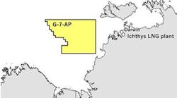
A specific design has been developed for the Bayu-Undan gas/condensate field, located offshore in the Timor Sea Zone of Cooperation between Australia and Indonesia.
Over the past several years, BHP and others have investigated the commercialization of offshore static gas resources. Options studied for these fields include methanol, synthetic fuels, and LNG. LNG production offshore could have significant cost advantages over onshore.
The advantages to locating cLNG operations offshore, versus on shore, are:
- An offshore facility would require only a short gas transmission pipeline, with minimal gas transmission costs. Gas can be made available at higher pressure.
- No land is needed for the plant site, eliminating the associated site development costs and environmental impacts.
- Costly infrastructure develop ment in remote areas is not required, such as community facilities, roads, con struction wharf, con struction camps, or harbor facilities.
- The offshore facility may be constructed at lower cost, with greater quality control at established fabrication yards, rather than importing high cost labor to the remote onshore plant site.
- Good quality seawater for process cooling is readily accessible offshore.
- Channel dredging, a jetty, and extensive cryogenic piping for the transfer of LNG from storage to the loading terminal is eliminated.
- The offshore loading terminal requires no LNG carrier operations in crowded harbors, nor any associated delays.
- In some cases, the offshore facility may be geographically closer to the customer, compared with the nearest suitable onshore plant site, thereby reducing shipping costs.
Timor Sea application
The Bayu-Undan gas/condensate resource is located in the Timor Sea Zone of Cooperation (ZOC) between Australia and Indonesia. The offshore cLNG design developed specifically for Bayu-Undan could have many applications elsewhere around the world.The development plans for Bayu-Undan call for a condensate and LPG stripping operation. Initially, lean gas would be re-injected into the reservoir until downstream gas utilization facilities (of which cLNG is one option) come on-line.
Weather conditions in the Timor Sea are generally benign, but subject to relatively immature tropical cyclones. It is in this area that BHP successfully pioneered the use of disconnectable and purpose-built floating production, storage, and off-loading (FPSO) oil facilities. FPSOs are now commonplace, even in areas with far harsher weather conditions than the Timor Sea.
Similar to the evolution of FPSOs for the commercialization of marginal oil fields, cLNG technology is now ready to use for the commercialization of marginal offshore gas fields.
Man-made islands
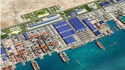
cLNG technology may one day be used on floating LNG facilities. However, floating facilities require the future development of a safe and reliable cryogenic offloading system for the transfer of LNG from one floating vessel to another.Fortunately for the near term, the availability of shallow water sites in the Timor Sea near undeveloped gas resources allows the cost-effective use of cLNG plants on gravity base structures (GBS). Such a man-made-island would sit firmly on the seabed. This enables the use of conventional loading arms for LNG transfer requiring no new LNG off load ing technology.
One of the critical aspects to consider in the selection of a liquefaction process for use in an offshore environment is safety. Although conventional liquefaction processes available today have been very successful in base-load plants, their extensive use of hydrocarbon refrigerants makes them less than ideal for use offshore. These processes have large inventories of liquefied hydro carbon gases, contained at high pressure, which would constitute a significant fire and explosion hazard for offshore applications.
A major concern is that such refrigerants could be involved in events such as bleves (boiling liquid expanding vapor explosions). These hazards are managed in a land-based plant by maintaining adequate separation distances between the equipment in the process plant, storage and off-loading areas, adjacent trains, and control room areas. However, in an offshore plant, it is not possible to maintain those same separation distances without the offshore plant becoming prohibitively expensive.
A basic principle of loss prevention and process safety is that the designer should aim to use small quantities of hazardous materials or substitute a less hazardous material if possible. Thus, BHP considered the inherently safer nitrogen cycle process as a good candidate for offshore LNG.
By using nitrogen as the refrigerant, the inventories of liquefied hydrocarbons contained in the process are greatly reduced. Further more, there are fewer equipment items and systems handling flammable hydrocarbons, and consequently fewer potential points for hazardous materials to leak from flanges, compressor seals, and other points. Each of these aspects reduces risk on the offshore LNG facility.
The nitrogen expander cycle process has been suggested by others for offshore LNG production, but it has generally been dismissed as being too inefficient for use in a base-load LNG plant.
Nitrogen process cycle
The nitrogen cycle process has a number of attractions for offshore LNG production. The simple design, using a single refrigeration cycle operating in the single-phase gas region, means that there are relatively few equipment items. The liquefaction section of the plant consists of a single compressor, a turbo-expander, a cold box, and three heat exchangers for the compressor coolers. This reduces the complexity and space requirements for the plant. No compressor suction or refrigerant surge drums are required, nor their associated piping, valves, and instrumentation.The disadvantage of using this nitrogen cycle process for a much larger base-load LNG plant is, however, the relatively low process efficiency of the cycle. The refrigeration power requirement (per kmol of LNG liquefied) for a typical small-size LNG peak-shaving plant using a nitrogen cycle (see accompanying chart) is over three times that of a base-load LNG plant using a mixed-refrigerant cycle.
It is clear that it would not be competitive to use a nitrogen cycle with this process efficiency for a base-load LNG plant. Furthermore, even if the large industrial "Frame 7" gas turbine were used as the compressor driver, the maximum throughput of each train would be rather small, because of this poor efficiency. The low efficiency of the nitrogen cycle process used in peak-shaving units is partly caused by the relatively low throughput of these units, compared to base-load plants, rather than being entirely due to the lower process efficiency of the nitrogen cycle process itself.
The efficiencies of the small rotating equipment used in peak-shaving plants are significantly lower than those of the larger equipment that would be used in a base-load plant. In addition, the feed gas pressure available to a peak-shaving plant may also be lower than the 55 bar pressure typically used in a base-load plant. This results in lower thermodynamic efficiency and contributes to the high refrigeration power requirement of the process.
This illustrates the improvement in efficiency if the simple nitrogen cycle process were increased in size to a much larger capacity and the feed gas pressure increased to 55 bar. Using typical efficiencies for large rotating machinery improves the cycle efficiency to approximately 11 kW/kmol/hr. However, this is still significantly more than for a conventional mixed-refrigerant cycle. One significant inefficiency in the nitrogen cycle is the use of the expansion valve in the nitrogen supply to the coldest exchanger. The adiabatic expansion across this valve results in a loss of ability to produce work from this high-pressure stream. In a small LNG peak-shaving unit, this loss of work is quite small in absolute terms and attempting to recover it is not justified.
For the larger scale base-load plant however, the improved nitrogen cycle that BHP and Linde have developed recovers this lost work by using a second, so-called "cold" expander in place of the expansion valve. This results in a significant improvement in efficiency (see accompanying table).
Pre-cooling the feed gas via a small auxiliary refrigeration cycle is another known way of increasing the efficiency of the nitrogen cycle, and this has been found to be the case for the cLNG process also - especially in applications with high ambient temperatures. The auxiliary refrigeration system is relatively small. Conventional chiller packages with "ozone-friendly" Freon refrigerants are used rather than a propane system. This maintains the safety philosophy for offshore applications.
By adding the cold expander, and by optimizing the temperature levels and load split between the warm and cold expander duties, a much closer matching of the heating and cooling curves between the feed gas and nitrogen refrigerant can be obtained. This results in higher thermodynamic efficiency.
The cumulative effect of these improvements is to reduce the specific power requirements to a competitive level for small to medium LNG plant capacities, and yet to retain all of the inherent safety and simplicity advantages of the simple nitrogen cycle.
Bayu-Undan process
For Bayu-Undan, a single train of pretreatment removes acid gases, water, and mercury from the lean feed gas. Two independent trains of liquefaction and refrigeration provide good overall availability and each train is capable of producing up to 1.5 million tons per annum of LNG using a single gas turbine driver per train.The lean feed gas is transported to the plant from the Bayu-Undan upstream facilities by a high pressure pipeline operating at an inlet pressure of up to 180 bar. Because the gas has already been processed to remove condensate and LPG in the field, the C5+ content of the lean feed gas is very low. Gas can therefore be liquefied without reducing the gas pressure for removal of C5+ hydrocarbons.
Of course, the recovery of make-up hydrocarbon refrigerants, as is usually required for a mixed-refrigerant process, is not required for the nitrogen cycle process. Thus, the cLNG process can take full thermodynamic advantage of the high feed gas pressure. The bulk of the feed gas is cooled at a pressure of approximately 83 bar.
The liquefaction/refrigeration unit for one train illustrates the simplicity of the cLNG process. Feed gas enters the top of the coil-wound heat exchanger and is cooled to approximately -90°C by nitrogen refrigerant flowing on the shell side of a coil-wound heat-exchanger (CWHE). A CWHE was chosen for Bayu-Undan because of the high feed gas pressure, as well as the high reliability of this type of exchanger. For lower feed gas pressures, brazed aluminum heat ex changers installed in a cold box could also be used.
The cooled, high-pressure natural gas is then reduced in pressure and sub-cooled with the coldest level of nitrogen refrigerant in two cores of brazed aluminum heat exchangers installed in a cold box. A nitrogen stripper column and reboiler is required to reduce the nitrogen content of the LNG product to less than 1 mol% because of the high nitrogen content of the feed gas.
For feeds with less nitrogen, a simple flash drum would be adequate. Flash gas from the top of the nitrogen stripper column is warmed with nitrogen refrigerant to recover the refrigeration potential of the stream and is then re-compressed to fuel gas pressure.
The cLNG process maintains the simplicity of the nitrogen cycle used in LNG peak-shaving units. Nitrogen refrigerant at a pressure of about 18 bar is compressed by a single nitrogen compressor in two stages to approximately 50 bar.
Seawater is used for inter-cooling and after-cooling. Both nitrogen compression stages are incorporated in a single-case centrifugal compressor directly driven by an aero-derivative gas turbine. For Bayu-Undan, the large aero-derivatives such as the GE LM-6000 or Rolls Royce Trent gas turbines may be used to produce up to 1.5 mtpa of LNG per train. Inlet air cooling with a chilled water system is used to maximize the power output of the gas turbines at the warm ambient air temperature encountered at the Bayu-Undan site.
The nitrogen refrigerant is further compressed to approximately 84 bar by the booster compressors of the warm and cold expander/ booster units. The high pressure nitrogen is then cooled with seawater and chilled water to approximately 10°C. The chilled water system is comprised of electrically driven Freon refrigeration units and supplies chilled water for cooling of the high pressure nitrogen, treated feed gas and inlet air to the gas turbines.
Cooled high pressure nitrogen then flows to the nitrogen tube pass of the main CWHE where it is pre-cooled with low pressure nitrogen to approximately -15°C in the first tube bundle. This cold nitrogen stream is then split into two portions and the larger portion flows to the warm expander/booster units where it is expanded to low pressure and temperature. This cold nitrogen stream flows to the shell-side of the main CWHE to provide the bulk of the cooling of the natural gas and high pressure nitrogen refrigerant.
The smaller portion of cooled high pressure nitrogen is then further cooled in the nitrogen tube pass of the main CWHE to approximately -90°C in the second tube bundle. This cold high pressure nitrogen stream then flows to the cold expander/booster unit where it is expanded to low pressure and a temperature of approximately -150°C which provides the sub-cooling of the natural gas in the brazed aluminum cores in the cold box. The nitrogen leaving the cold box joins the larger nitrogen steam coming from the discharge of the warm expander/ booster units and flows to the shell side of the main CWHE.
The machines used for both the warm and cold expander/booster units for this train size are large, but are still within proven experience ranges for the manufacturers.
Gas conversion efficiency
The gas conversion efficiency (heating value of the LNG product to storage divided by the heating value of the feed gas) of the above process is 92-93%.This result is very satisfactory given that the specific power requirements of the process are still approximately 25% higher than a typical onshore base-load plant.
Copyright 1998 Oil & Gas Journal. All Rights Reserved.


