Skid-on, float-over, sand jacking options to heavy lift
New methods for heavy structures
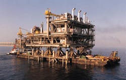
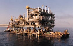
The float-over method used by JRM in the Persian Gulf shows the Mobil Ras Laffan PU Deck during alignment of the complete deck and superstructure with the jacket before lowering.
Heavy lift alternatives for installing decks on floating and fixed structures are being developed by J. Ray McDermott, Inc. (JRM) The goal is to provide single piece integrated decks, fully commissioned onshore, with the inherent advantages of reduced cycle time, earlier production, and reduced cost.
Historically decks weighing from 7,000 tons up to 25,000 tons exceed single crane lift capacities and are typically installed in multiple pieces, resulting in offshore hookup and commissioning. In some areas of the world with access to smaller crane barges this threshold can be as low as 1,000 tons.
Recognizing the advantages of integrated decks, JRM is evaluating all the existing and proposed methods to develop alternate heavy lift solutions. This initiative has identified a new Skid-On method for installing a large deck on floating structures such as a spar or tension-leg platform (TLP). Another floatover method for installing integrated decks on jackets has actually been developed and used successfully twice this year.
Skid-On method
The Skid-On method utilizes a single barge to both transport and install large topsides. The transport barge, typically a launch barge for stability and strength requirements, is docked to the spar offshore with the marine connector. The topsides are then skidded across onto the spar hull.The marine connector (patent pending) is a robust mechanism that allows only relative pitch motions between the barge and spar hull. The Skid-On can accommodate the heaviest anticipated topsides, with capacity in excess of 20,000 tons.
Wave basin model testing has shown that docking, skidding, and disconnect can be accomplished offshore, even in swell conditions typical for West Africa or Brazil. Skid-On technology will be available to the industry for use in 1999.
Floatover system
JRM introduced its floatover system in the late summer of 1998 in the Arabian Gulf off Qatar. The Mobil Ras Laffan PU Deck, at 5,000 tons, and the Qatar Gas PR Deck, at 4,000 tons, were installed successfully with this system.The new floatover system proved simple to rig up, test, and operate. The design maxim was "simplicity offshore, complexity onshore." A system that is easily maintained and tested in a marine environment, and is simple to operate offshore may require complex design, analyses, and planning onshore. Simplicity is a major contributor in insuring system reliability.
Additional reliability derives from robust system components designed for the most extreme sea state criteria for which floatover operations are allowed to proceed. The system is designed to avoid the development of large reactions during the floatover, rather than resist large reactions once developed.
Large reactions in the horizontal plane are avoided by partially restraining, but not stopping, the relative motion between the barge and the jacket. The design of the components of the floatover system require a good understanding of the relative motions between the barge and jacket, so much so that the system is termed "motion based."
The barge is held in the final floatover position by two separate mooring systems that allow relative motion between the barge and the jacket. An eight-point catenary mooring system resists steady state environmental forces from the wind, current and wave drift.
A soft line mooring system is installed between the barge and the jacket legs to resist suddenly applied forces from wind gusts and broken mooring line contingency cases, and to reduce the excursions from cyclical slow drift. Soft line mooring system stiffness is targeted for these loads only keeping the forces against the jacket legs small. The expected motions of the barge from all sources produce an acceptable jacket "slot" width. Because relative motion is permitted in the slot during the entire floatover operation, the JRM system is sometimes termed a "loose slot" system.
Once in position the system will transfer the deck to the jacket while compensating for forces and impact for wave induced motions. As the barge is ballasted downward, cylindrical telescoping rams projecting below each deck leg land on flat horizontal surfaces, "flat tops," mounted on the top of the jacket legs, or main piles.
Low friction contacting surfaces are provided to limit friction forces from the rams sliding on the flat tops. The flat top diameter is large enough to accommodate the expected horizontal motions of the sliding ram plus an appropriate safety margin. The friction forces acting on the flat tops, plus the reactions from the soft line mooring system, are much smaller than what would be produced by locking the barge into the jacket slot, or the platform deck into the jacket during the floatover.
As the deck lands on the jacket, the telescoping rams react against a stack of rubber disks inside each deck leg. Thus, the axial load in the rams is limited by the rubber disk stack, as determined by its load versus distortion relation. This eliminates any vertical impact loading as the deck lands on the jacket.
Motion-based system
As deck and barge sizes increase, relative motions between the barge and jacket decrease, but the forces for any system that locks into the jacket would increase. JRM opted to develop a motion-based system, because the reactions imposed on the jacket and deck are small and the situation improves with barge and deck size. These features should make the system adaptable to the various needs of prospective clients.The flat top is the top of a piston inside a "sand can," which is the top of a main pile, or jacket leg. Once the floatover is completed, the sand is drained through the valves causing the piston to travel downward stabbing the deck legs into the sand cans. Girth welds of deck legs to sand cans complete the deck installation.
Sand jack
The sand jacks support the deck during fabrication, loadout and tow, and collapse on demand to provide a rapid separation between the platform deck and the barge at the end of the loadout. The sand jack is an integrated system of load spreading shoes, tiedowns, and a sudden collapse structure. It is provided with two large doors that can be opened with a triggering system. The doors are large enough such that one will suffice, even with damp sand.The piston of the pneumatic impact jack strikes the removable trigger bar which lifts the trigger plates releasing the doors.
The trigger bar projects beyond the ends of the trigger plates and slides out of its supports for easy removal. Without the trigger bars, the entire system can be tested by firing all the jacks simultaneously. An impact jack is provided on each end of each trigger bar. So the design provides redundant doors and redundant impact jacks on each door to increase the reliability of the system.
To further enhance the reliability of the floatover system full size prototypes of each of the floatover system components were tested during the design. Among many other things, testing showed how to design and operate sand jacks so that the pistons would not get jammed. Finally, Lloyds was engaged to review the detail design of the components, their function as an integrated system, and the design procedures that we developed to check the platform components, when its deck is installed using the JRM floatover system.
Copyright 1998 Oil & Gas Journal. All Rights Reserved.


