Hanger system allows expandable patches, liner hangers
Frank Hartley Drilling/Production Editor
Expandable tubular technology has in recent years proved to be effective for liner hangers as well as casing repairs, according to Tommy Van, TIW regional salesman.
“Initially, we were looking for expandable technology that would give us the hanging capability for both short and long liner applications that also would give us a HP/HT seal at the liner top,” Van says. As a result, TIW design engineers and operational personnel designed and tested a new expandable hanger concept called the X-Pak Expandable Liner Hanger System.” It uses a tie-back expander working in conjunction with the X-Pak Hanger Body, and when set, forms an HP/HT seal.
Expandable liner hanger
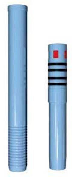
The system operates by using a hydraulic setting tool that presses the tie-back expander into the hanger body. Once hydraulically forced into the hanger body, the expander stays in place, forming a metal-to-metal seal between the two members.
“This action expands the hanger body out against the base casing, providing a metal-to-metal HP/HT seal between the three components, the expander, hanger body, and base casing. The system incorporates an integral tieback receptacle that requires no threaded connection, which can be used for future tie-back purposes,” says Van.
There are two ways of setting the tool. With the cementing process, when the plug is bumped, additional pressure is applied to expand the hanger. With plugs bumped and cement in place, pressure in the drill pipe shears a sacrificial tension ring on top of the hydraulic setting tool, allowing the power sections to expand the hanger body.
The drill-down liner hanger system is designed for use in drill down or rotational liner settings.
The tension ring allows the engineering of the expansion initiation pressure and eliminates the possibility of premature expansion in the drilling mode. The next step is to release from the liner by activating the auto release mechanism (ARM). Once the hanger is set, all that is required is to slack off the liner weight plus approximately 12 in. of drill pipe and automatically latch up the ARM without any rotation needed. At this point, you can pick straight up and release the drill pipe and setting tool from the liner, Van says.
The second method of setting the system is by dropping a setting ball down to a ball seat at the base of the setting tool.
“We will use this only as a secondary method, when or if, the liner wiper plug does not bump,” Van says. “A secondary method for release has also been incorporated into this system. If the ARM fails to release, rotational release is available. If needed, the drill pipe is rotated 22 torque free turns to the right, at the tool, which releases the setting tool from the hanger body and the liner. Once this is accomplished, then the drill pipe is pulled out of the hole.”
First applications
In April, 2004, Shell agreed to test the concept in critical highly deviated wells in the Gulf of Mexico and South Texas. They required the system to have the ability to rotate, drill and ream hole.
“The major requirement was our equipment to handle a minimum of 12,000 ft-lb of torque to handle the drilling process w/ a 5 1/2-in. liner,” Van said.
The 2T XPatch System is a two trip system designed to patch, with conventional tubulars, virtually any length desired.
Implementing his ideas with the X-Pak System, the Drill Down System was born, Van said. The first test of the ELH Drill Down System would be deployed on a land rig in South Texas. The McAllen #B-52 well in South Texas was designated for the first run of the equipment, with a liner size of 5 1⁄2-in. and 17-lb P-110 Hyd-513 to be run inside 7 5/8-in. 33.7-lb casing. The intention was to run the equipment with drill-in technology, as the first step on the development staircase, despite not expecting to need the drill-in feature.
The liner went to bottom with no problems and was rotated as planned without complications. Torque recording was documented at various RPM. All indications were a sign of a good test. Shortly afterwards, the well was cemented, plugs bumped, the expandable hanger set, a 50,000-lb over-pull to verify set was performed, the liner top was tested to 20-ppg equivalent mud weight, slacking off on the drill string, activated auto release, and the setting tool and drill pipe were pulled out of the hole.
Second application
In the second application, TIW was asked to drill 1000 ft of new 6 1/2-in. hole with the 5 1/2-in., 17-lb liner.
“We tackled this application with a lot of enthusiasm,” Van said. “TIW developed a tool that would withstand 12,300 ft-lb of torque. Shell ran the equipment, drilled down 945 ft of new hole, at which point the liner point was reached. So, they circulated bottoms up, cleaned the hole, cemented the well, expanded the liner hanger in place, tested liner top to 20-lb equivalent, and auto released from it. The first two jobs went perfect. The ROP for this well was 14.5 ft/hr. for a total time of 65 hrs.
Third application
Shell torque requirements were high for the directional wells in the GoM. Shell’s requirements went from 12,000 ft-lb to 18,000 ft-lb of torque. TIW took the same 5 1/2-in setting tool and tested it to 22,200 ft-lb.
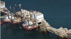
“After the test, we told Shell we could do the job,” Van said. “Shell’s requirements for us were to build and ship in 18 days. We met the objective and the tool arrived at the Brutus TLP for the A-7 sidetrack well. We did not have to drill it down but did rotate on bottom with 14,500 ft-lb of torque initially.
After Shell’s initiated rotation at 25 RPM, torque dropped to 9,500 ft-lb of torque.
After circulating bottoms up, The crew picked up and attached the cementing head, and during this operation, the liner got stuck. After two attempts to rotate at 22,000 ft-lb of torque, the drill pipe was brought back to neutral and circulation was established to clean hole before the cementing process started.
A fifth successful down-hole installation for a major Gulf of Mexico operator.
“We started the cementing job, pumped the cement, displaced the plugs, bumped the plugs on the landing collar at displacement, pressured up to 5,000 psi, set the liner hanger equipment, pull tested and then again released our setting tool by the auto release mechanism,” said Van. “At this time, Shell tested the Brutus A-7 well to a 20-ppg mud weight equivalent for the liner top test.”
Expandable casing patch
As a precursor to the development of the X-Pak ELH System, TIW was contacted by another operator and asked to design a one-trip expandable casing patch system that would meet three primary objectives,” explained Sam Baker, TIW Director of Marketing. “The first objective was that the pressure integrity of the patch, both internally and externally, must be as good as the casing in which it was set. The second objective was that the inside diameter of the patch must be of sufficient size to allow passage of ‘run through’ tools for remedial purposes and not reduce the flow area of the well. The third and final objective was to meet extreme cyclic thermal conditions that were anticipated by the operator.”
To satisfy the first objective, TIW considered several designs. It was known that current metallurgical properties of oil country tubular goods (OCTG) are readily expandable, and the burst ratings of post-expansion pipes are typically higher than pre-expansion due to work hardening. However, the collapse ratings of post-expanded pipes are much lower due to the increased D/T (Diameter over Thickness) ratios.
The design team concluded that to meet the requirements of the first objective, the patch would require an increased cross-sectional area to reduce the D/T ratio. Increasing the cross-sectional area would not be permissible, because it would not allow the design team to meet the requirements of the second objective, which was to have as large an inside diameter as possible. The third objective was to meet extreme cyclic thermal conditions, which proved to be the most challenging and design-altering objectives.
After the design team’s careful consideration, a new design concept was taken, one that would ultimately utilize both new as well as current technology.
Initial patch design
“A one-trip system was desirable by the operator, but it was discovered that the design of such a system had several disadvantages” says Baker. “TIW’s use of an inner string required to simultaneously set the upper and lower patch was critical, not only with regard to the length of liner, but also because it created field compatibility, handling and running difficulties.”
In slim hole sizes, compressive forces generated during the setting sequence of the upper and lower patch in some cases exceeded the compressive strength of the liner connections, causing the connections to partially collapse. Finally the design team had to overcome the challenge of thermal expansion and contraction of the “patch liner” and still maintain a fixed upper and a fixed lower tubing-to-casing seal.
The design team asked, “What if we subject the actual patch body to a plastic state, but support it internally with a non-expanded mandrel?” This was considered a feasible solution; the problem of pressure integrity along with the full opening requirements could be met with this concept.
“Liner tie-back receptacles and tie-back stems are nothing new to the industry,” Baker noted. “Experience has shown that tie-back stems with elastomeric seals and/or metal-to-metal seals have long proven successful in down-hole tie-back scenarios in both normal and elevated temperature environments.”
Recognizing this fact, it was decided to use a metal-to-metal seal tie-back design within the casing patch that would not only satisfy the full bore opening requirements but also allow a dynamic seal for the anticipated thermal contraction and expansion. The design team made the decision and the two-trip casing patch system was born.
“As opposed to the one-trip system, this assembly was comprised of a lower patch body, and an expander, which incorporates an integral tie-back receptacle,” Baker said. The tie-back receptacle also serves as a packer bore receptacle, which accommodates for thermal expansion and/or contraction of the patch liner, thus eliminating the expansion joint required in the previous one-trip designs. Also, after setting the lower patch, virtually any length of patch liner could now be run, due to the elimination of the inner string.
“Incorporating lessons learned and including the new designs, which eliminated compressive forces during the setting of the upper and lower patch, plus the hydraulic setting tool in a one trip system, resulted in the 2T XPatch system,” Baker said. The system, he says, allows the ability to patch with conventional tubulars with virtually any length and the largest inside diameter. The full opening ID permits the passage of future service tools through the patch.
“As we look to the future of well bore construction, we view the combinations of casing drilling, expandable liner tops, and mono bore well designs as the most viable and economical means of reaching TD’s that are inevitably getting deeper, more complex and thus more expensive to complete,” Baker says.
Technical questions about the system
How does this hanger differ from the rest of the industry?
The design provides HT/HP seal as well as ultra hanging capacity. The equipment is designed with P-110 casing and testing with Q-125 material. TIW doesn’t expect any special metallurgy or other special casing needs. It currently uses N-80, L-80, and P-110.
What is the maximum percentage of expansion?
It has gone to 22% - 24% and can expand to any casing size needed. The only restriction is getting into 3 1/2 -in. inside 4 1/2-in. or 4-in. inside 5 1/2-in., because you can’t cement the job, but you can run and cement in 4 1/2-in. inside 7-in. as well as larger conventional liner sizes.
How deep have you gone with this system?
The maximum depth so far is 21,229 ft. The tool offers full burst and collapse parameters of the tubulars by leaving the expander in place. TIW currently has 5-liner hangers in the hole.
Who is using the X-Pak ELH System?
Shell, BP, Forrest, and Anadarko are using the Top Drive Cementing Manifold in conjunction with the double ball plug dropping head with internal by-pass system. For highly deviated or horizontal holes, a specially designed offset nosepiece was designed to assist the liner through ledges and doglegs.
