Rotary steerable technology extends well in difficult geology
The rotational attitude of the outer housing has been monitored through a variety of inclinations, both during drilling and tripping.
Three-dimensional rotary steerable technologies continue to gain momentum. Increased reliability and reports of huge gains in drilling efficiencies are driving heightened interest in these technologies. Large and small service companies alike are getting into the action, providing uniquely designed and configured commercial rotary steerable systems. Rotary Steerable Tools (RST) has patented, designed, and built a rotary steerable system capable of a stand-alone service, or with the option of a MWD/LWD provider, directional drilling, bits, and other services from a third party service company of choice. The tool is a very simple, ruggedly constructed design offering complete three dimensional, well directional control.
The advantages of steering directional wells with three-dimensional rotary steering tools have been the subject of many recent articles. In all cases, three-dimensional rotary steering is accomplished by one of two means:
- Applying a force to the side of the bit (Side-Force) and/or,
- 2. Pointing the bit (Point-the-Bit) through a shaft/BHA (bottom hole assembly) deflection device.
Proper orientation of the side force and/or point is maintained through the use of sophisticated directional sensors with feedback circuitry or by simple mechanical means.
Point-the-Bit and Side-Force Methods
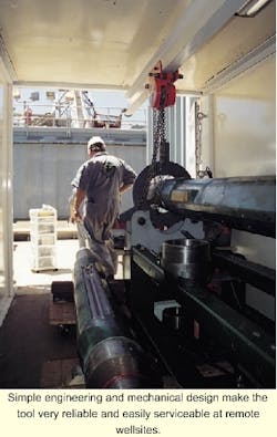
Simple engineering and mechanical design make the tool very reliable and easily serviceable at remote wellsites.
The current commercially available rotary steerable systems are configured to operate in a Side-Force or Point-the-Bit mode. The RST device has the flexibility to be configured as a Point-the-Bit and a Side-Force device. Pointing the bit has many operational and trajectory advantages over a pure Side-Force rotary steerable system. George Sutherland, Executive Vice President of Rotary Steerable Tools, stated, "Pointing the bit will drill a more predictable and smoother curve, with less "ledging", it also gives a wider choice of bit selection, as the RST tool is not limited to use with specialized "side cutting" bit designs. Point-the-Bit devices should also be less susceptible to hole washout."
The RST system offsets and points the bit, utilizing an eccentric inner sleeve, "cam", located in the tool a few feet behind the bit. This points the bit/BHA and also applies a bit side force in the desired direction of wellbore movement. The cam orientation is maintained by gravity orientation of an outer, mass-weighted housing. This is a simple design, using the earth's gravitational force to orient and maintain "high-side" tool orientation. A slightly under gauge sleeve type stabilizer, or an integral blade stabilizer is run immediately above the RST. This stabilizer has the dual advantage of isolating the weight force of the BHA from the outer housing, and also providing reaming and improved hole cleaning immediately above the RST tool, approximately 14 feet from the face of the bit. Back-reaming, and reaming and washing to bottom have proven effective with this assembly.
Dogleg severity or curve characteristics are rig site selectable through selection of the appropriate cam offset. The adjustment is made off the rig-floor and takes less than one hour to make. This is similar to the way that a driller would select the correct bend angle on the bent housing of a steerable motor. The cam offsets for the 12 1/4-in. hole size, vary from 1 mm to 10 mm and should provide build/turn rates from 0.3°/100 ft to 7.5°/100 ft. This is in line with the maximum build rates that are attainable using "sideforce" rotary steerable tools.
Once the dogleg characteristic has been selected, the make-up procedure is simple. The tool is conveyed to the drillfloor and made up to the bit. The uphole end of the tool is made up to an undergauge stabilizer, then the MWD/ Surveying device of choice, and after torquing a single internal connection, the assembly can be tripped-in the hole.
The RST device was designed to be extremely simple to fabricate and maintain, and robust in construction. Particular emphasis was placed on utilizing simple, proven components, and maintaining a "user friendly" design.
Downhole tool communication via rotary speed
The tool utilizes a unique method of downhole communication, making the tool fully compatible with any other drillstring components. This compatibility was one of the original design criteria. A second advantage to this method of communication is the ability to send complex instructions to the downhole tool over a very short time period. Although this is not being utilized in the current version of the RST tool, later versions will exploit this advantage with more sophisticated program abilities and the incorporation of additional sensors.
Modern MWD tools and other BHA components traditionally utilize weight on bit, mud pressure, or flow rate for downhole communication. In contrast with these methods of communication, instruction of toolface to the RST tool is accomplished, by varying rotary speed over a 3 1/2 minute time interval. However, this does not mean that there are specific rotary speeds to be avoided, but rather, the tool is commanded by varying the drillstring speed over pre-determined time intervals. The drill string can be continuously rotated, reciprocated, and circulated during tool instruction. Once a toolface command is downlinked, the cam is oriented with an aerospace quality electric motor and locked into position. Drilling is then resumed.
Operational Limitations
When using the tool within normal drilling parameters there are no restrictions on weight on bit, rotary speed, or flow rate, the three most common parameters used to influence rate of penetration.
Minimizing pressure drop through drilling tools can prove beneficial, especially in extended reach situations where hole cleaning issues come into play. Steerable motors and 2D rotary systems can, in some situations, take up to 30% of the total pressure budget of the circulating system. The RST tool in a 12 1/4-in. hole exhibits similar pressure drops to a standard drill collar. Company President Steve McLoughlin stated "The ability to offer 3D trajectory control with such a radical improvement in wellbore hydraulics will have a big impact on directional drilling. The higher ROP associated with rotary steerable drilling is of no use without adequate hole cleaning. Using the RST tool means that smaller capacity rigs can now be used to drill much more challenging directional wells with less risk."
Easy field serviceability
The tool has been designed to be almost completely field serviceable. RST recognized early in the development of the tool that the "remote" nature of the oil business, where service facilities are scarce and the cost of transportation is high, demanded a tool that requires little, to no maintenance. Accordingly, some of the design effort was focused on the ability to service the tool in the field. The rig footprint of the mobile service facility is small (less than 60 sq ft), consisting of two tool baskets, and a remodeled offshore shipping container. Batteries, electronics, and bearings are field serviceable without draining the internal hydraulic reservoir. These constitute the major wear and consumable components of the tool. Every external bolt on the tool is encapsulated or backed-up by snap rings, helping to minimize damage to critical mechanical parts. The mandrel, which transmits all of the torque and weight to the bit, rotates in marine grade radial and thrust bearings that are rig site replaceable.
The tool electronics are housed in the non-rotating, mass-weighted housing. This means that the electronics assembly is not subject to centrifugal forces during drilling, and provides the electronics with a much smoother ride. In addition to receiving surface RPM commands and driving a motor to control cam orientation, the electronics also record large amounts of diagnostic data. Many diagnostic parameters including motor current, battery voltage, and housing orientation are recorded. Once back at the surface, this information is downloaded to a laptop computer for analysis. The diagnostic and programming system is confined to a laptop computer, surface interface box (smaller in dimension than a laptop computer) and some associated cable connections. The tool can be made fully functional within half-an hour.
Extended reach well in low drillability geology
Testing runs have been made at the former Amoco/PD Catoosa Drilling Technology Test Facility, confirming the tool's ability to correct the course of the wellbore in three-dimensions. A commercial test job was more recently performed for a major operator offshore California. Past well experience in this area had shown very difficult drilling in some of the geologic sequences encountered. These formations had not been penetrated at such a high well bore angle. Extended reach well designs were proposed to drill a reservoir extension into several separate fault blocks, as much as 30,000 ft away from the existing platform, presenting new and significant challenges. The operator decided to utilize the existing platform structure and extended reach drilling (ERD) technology to exploit these long reach reserves in order to save the cost of installing additional infrastructure.
One of the biggest challenges of this well was directional control of a long tangent interval in 12 1/4-in. hole size. This 15,000 ft interval would traverse several formations with varying degrees of drillability. Previous wells in this area, with much less horizontal displacement, had experienced difficulty in directional control although conventional steerable motor and rotary assemblies had achieved some success through an effective trial and error approach.
The planned ERD well would reach a point of "negative weight" approximately 1/3 of the way into the 12 1/4-in. tangent. At this point, the ability to transfer weight to the bit while sliding an oriented motor would become extremely difficult - if not impossible. The decision was made to avoid motors and rotary drill the entire interval. The RST tool would be used for three-dimensional trajectory control where necessary. A final steerable motor run was planned for just prior to reaching the point of negative weight, with the objective of lining the well up on target before drilling ahead with rotary assemblies. Drilling with rotary assemblies would allow for rotation of the entire drill string, having the effect of reducing axial friction forces and improving weight on bit transfer for the remainder of the well interval.
The operator ran the rotary assemblies, with adjustable gauge stabilizers and specialized bits to control both inclination and azimuth for several thousand feet with success. Before picking up the rotary steerable tool however, the wellbore began drifting to the right of the planned well trajectory. The rotary steerable tool was placed in the hole at a toolface position of 60° left of high side, the tool drilled 125 ft, turning and building the wellbore at 3.1°/100 ft. An average response of 2.0°/100 ft build, and 1.8°/100 ft left turn was noted on this first interval, which was drilled utilizing a 4-3-7 insert bit.
The RST tool drilled a further 493 ft, utilizing insert and PDC bits, gathering tool response and diagnostic data, and confirming the tool's ability to steer a wellbore in 3 dimensions. The directional data obtained from MWD and downhole tool memory confirmed proper tool directional response to the inner sleeve cam positioning. The data clearly demonstrated the ability to change, and maintain, inclination and azimuth effectively. Curvature averaged less than 0.6°/100 ft over this tangent interval.
All bit runs were made using the same BHA. The RST tool was run directly behind the bit with a 12 1/8-in. string stabilizer run immediately above the tool. Another string stabilizer was placed 31 ft above the 12 1/8-in. stabilizer. The BHA was very effective at turning, building, and dropping wellbore trajectory. As is expected in a dropping assembly, the doglegs encountered were of slightly lower magnitude.
Simple design yielding favorable tool reliability
One trip was made for the tool when directional response was other than expected. At surface, the cam position was found to be consistent with the directional response of the wellbore and the tool also confirmed that RPM commands were received correctly. Inspection of the RST tool components indicated that the cam may have moved downhole without being instructed to do so. The software configuration was not set up to report misalignment of the cam. Subsequent hardware/software revisions have strengthened the cam brake, and allowed for automatic correction of any uninstructed cam movement.
Tool diagnostic data showed better than expected battery life. Battery consumption was only 17% after 127 hours. One reason for the better than expected battery life, demonstrated by the recorded diagnostic data, is that battery voltage improves with increased temperature. Using the electronics configuration used in this well, it is believed that the RST tool can run for 232 straight hours before requiring a battery change.
Diagnostic data also confirmed successful tool communication. Downhole communication was over 85% successful on all bit runs and confirmed the effectiveness of the rotary, RPM, method of communication at depths greater than 19,000 ft. Improvements to software processing and filtering should continue to improve on these early results.
The RST tool requires low side orientation of the mass-weighted housing in order to maintain proper toolface orientation. Accelerometer data was collected that demonstrates extremely reliable low side orientation of the housing during drilling.
The mechanical and electrical integrity of the tool has proven extremely sound under challenging drilling situations. Thrust and radial bearings showed minimal wear of less than 0.001 in., despite being run in a hematite-oil based mud system. All seals and O-rings performed as anticipated and there were no signs of mud invasion. The compensating pistons performed as expected with the tool showing less than one percent oil loss, or air collapse during all runs. No adverse effects were observed despite relatively high flow rates. The electronics showed no signs of shock/vibration or other impact damage and full electronic communication was established on the surface with 100% data retrieval after each run in hole.
The company has spent over two and one-half years designing and building two 12 1/4-in. hole size prototype tools. The company continues to make minor tool modifications and improvements, particularly with regard to ease of assembly and dis-assembly. Several more 12-1/4-in. hole size tools are being manufactured and plans are already being implemented to downsize the technology for 9 7/8 in., 8 1/2 in., and 6-in hole sizes as rapidly as possible. Specialty hole sizes such as 10 5/8 in., and 14 in. will be provided for by special arrangement with individual operating companies.
Acknowledgements
G. Sutherland, Executive Vice President, Rotary Steerable Tools
S. McLoughlin, President, Rotary Steerable Tools


