Piled jacket solution addresses soil concerns for Gulf of Suez minimal platform
Extended sleeve arrangement for topsides setdown
Stewart Maxwell
Aquaterra Energy
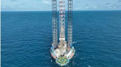
Conductor-supported platforms, which are designed for benign, shallow-water locations such as West Africa and Southeast Asia, are also an alternative to traditional platforms and subsea trees for the Gulf of Suez offshore Egypt. They have shorter lead times in terms of delivery, incur lower intervention and platform costs, and have a much simpler project management process. Another benefit is that the platform can be installed by the same jackup rig contracted for development drilling at the site.
The Gulf of Suez is located at a junction of the tectonic plates of the northeast African continent and the Arabian Sinai peninsula. Seismic activity in the region can be of sufficient intensity to drive the design of an offshore platform to be installed in the region. Egyptian operator Amal Petroleum Co.’s Amal field is in the southern part of the Gulf of Suez in the middle of the channel alongside the shipping lane. Water depth at the mid-channel location is typically 60 m (197 ft) or above; however, the water depth over the Amal field shallows to around 23 m (75 ft), due to a localized high-carbonate content calcareous formation. This is soil that is essentially comprised of crushed shell and coral fragments.
Aquaterra Energy, which has been delivering its own minimum facility, conductor-supported platform solution called Sea Swift for over a decade, won a contract in 2015 to engineer and deliver a new minimum facilities wellhead platform for installation on the Amal field. The company uses its in-house developed structural engineering modeling software and analysis to determine system strength and stability and the design fatigue life of each Sea Swift with location-specific metocean and geotechnical data. It also has a track record of rapidly adapting and engineering its platform solutions in response to major changes in design conditions that sometimes arise during project delivery.
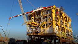
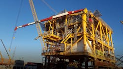
Amal on the dock. (All photos courtesy Aquaterra Energy)
In the case of the Amal-C platform substructure and pile foundation design, new soils data and latest industry practice soils interpretation obtained during the detailed engineering phase meant the conceptual engineering solution was no longer viable at the location. An augmented platform foundation would therefore be needed to cope with the revised geotechnical data, and this was confirmed by the recent foundation strengthening campaign that the operator performed on the nearby Amal-B platform.
From the outset, the key design driver of any platform arrangement in this type of location and with this type of calcareous formation must be to manage the foundation interaction through the notoriously challenging soil, and for this project, compiling high-quality site location soil data would be paramount.
Conceptual engineering based on design soil profiles that had been provided at the start of the project had indicated a reduction in pile shaft friction resistance through the calcareous soil layers compared with more usual siliceous sand soil types. With the foundation design checks safely within code limits, a conductor-supported platform configuration remained the best and most efficient solution for the project, and engineering design therefore proceeded at a pace to meet the project delivery schedule. The company developed conductor leg, subsea structure, and topsides framing design arrangements taking into account platform loading conditions, offshore installation, future workover interface tolerances, and design constraints.
In parallel, the company requested the driving and drilling logs from the adjacent Amal-B platform to support its understanding of the soil conditions in the immediate vicinity of the new platform location, because the supplied geotechnical data had been partly derived from borehole samples from a nearby offset location. While these logs allowed calibration of the existing sample data to develop reliable pile drivability and driving fatigue assessments, they also revealed that the soil again weakened below the borehole sample depth, a factor that could severely constrain foundation design options. The drivability assessments concluded there would be a high risk of pile run occurring throughout the piling operation, and this led to the development of appropriate contingency procedures for the offshore pile installation.
Due to historical issues with conductor pile performance at Amal-B, an independent geotechnical data interpretation study was commissioned using current industry best practice guidelines for interpretation of high carbonate content soil/pile interaction. The assessment showed that further significant reduction in pile foundation performance was likely over the original design soil profiles, which in turn shed more light on the client’s experience with Amal-B and led the project team to a key decision point.
With multi-discipline engineering design fully under way and a major step change in soil conditions now apparent, the challenge was to quickly find the best overall platform solution for the client’s approval. This would need to have a minimal impact on progression of the facilities layout and design and on the fabrication schedule, considering the Egyptian fabricators’ long lead material procurement cycle.
Ultimately maintaining the tight offshore delivery schedule was the client’s key requirement to prevent the offshore construction campaign from slipping into the winter months when onerous wind sea conditions could further delay platform start-up.
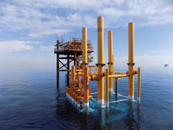
Amal C jacket installed.
Revised solution
Conductor-supported platforms, by the dual-purpose nature of the conductor piles, rely solely on foundation axial capacity generated by pile shaft friction resistance. Disturbance of the internal soil plug by installation of the well casings means that the final contribution of end bearing resistance cannot be determined reliably, and so is not normally considered. The new soil interpretation revealed that pile shaft friction would be extremely compromised at this location, and the drive logs indicated that simply increasing pile penetration would not be effective, as the required pile extension would be extreme and into weak and untested soils.
The primary option to preserve the conductor-supported platform concept with minimal overall impact on the project was to enhance pile skin friction by changing to a drill and cement conductor installation method. Grouting the piles into the porous carbonate foundation would provide a very good foundation capacity, although grout losses into the formation were both a concern and the basis for achieving improved pile shaft resistance if grouting were successful.
Grouting piles are the industry best practice installation method for piles in calcareous soils and are commonly used offshore Western Australia where this soil type is prevalent. Unusually for a Sea Swift CSP installation project, there were no plans for a drilling rig to be on site during the platform construction phase. The well drilling campaign on Amal-C was scheduled for a future development phase, and further consultation with the client confirmed that no other viable methods to drill and cement the piles were available, so this particular option was discounted for the project.
With topsides facility requirements increasing as the project went on, few opportunities arose to reduce topsides weight and foundation loading. It was clear that weight reductions that were made would not be sufficient to compensate for the lack of soil support, and so adding more foundation piles would be the next viable option. Making the inboard conductors part of the platform structural foundation did not adequately increase the foundation capacity where needed, so the team assessed options for adding secondary piles. The main benefit of using secondary (non-well bearing) piles would be the ability to account for the pile’s full end bearing resistance: two design variants were therefore proposed.
The first design proposal involved adding secondary piles to the existing subsea structure. This option offered the minimum structural change compared with the original concept, but still required the primary well conductors be installed to support the topsides. With the future well drilling campaign in mind, the preference was to minimize the initial number of required pile installations where possible. The second design proposal would involve extending the primary conductor pile sleeves to the surface, essentially forming a narrow-legged jacket arrangement on which the topsides could be set using the normal Sea Swift landing interface. This arrangement would also provide traditional benefits such as pre-installation of boat landing and risers onshore.
Conclusion
The Aquaterra Energy project team presented its solutions to the client and, based on the Amal-C platform’s functional requirements, recommended the secondary pile jacket solution. Having obtained the client’s agreement, the jacket and foundation design engineering then proceeded against the recovery plan to ensure delivery of the original material take-off and primary steel design schedule.
The company was able to identify in advance a major project roadblock and successfully navigate around it, with no impact to topsides design engineering or to the fabricators’ material procurement schedule. The Amal-C platform and foundation structural design fulfilled all functional and international standards performance requirements defined for the project and were reviewed and approved by Bureau Veritas.
This is the first Aquaterra Energy platform to be founded on challenging calcareous soil, with the design driven by regional seismic activity. It was designed as a hybrid structure using conventional jacket structural arrangements with driven (as opposed to drilled and cemented) conductor leg piles. •
The author
As Technical Director, Stewart Maxwell is responsible for the Offshore Structure products within Aquaterra Energy, as well as driving technical innovations across all parts of the business. He has held positions in Asia/Pacific and the UK throughout his career and has been involved with the analysis, design, engineering and installation of riser and conductor systems (shallow and deepwater), minimum facilities platforms, bespoke offshore engineering and offshore problem solving. Before joining Aquaterra Energy, Stewart spent 13 years with the Acteon Group of companies, in various positions including Regional Director – Asia Pacific and Global Manager – Conductor Systems. He has also worked at Nio Petroleum and Enquest, as well as establishing his own engineering consultancy in riser and conductor analysis, well integrity and project management.
