Deepwater construction takes the next step
A graphic progression of pipelaying into deeper water (Figure 1 [37,395 bytes]) shows these early achievements remained unsurpassed for more than 10 years (in terms of water depth) until the reel ship Apache laid a 10-in pipeline for Petrobras in the Campos Basin in 705 meters water depth, according to Saipem.
The trend is clear - more deeper water projects from the mid-1990s and significant jumps as the industry moves into the new millennium. However, it is important to note that some of these latter day achievements, although significant have mostly involved smaller diameter flowlines, in the range 10-12 in., with the exception of the Shell Mars 18-in. pipeline.
With this in mind, it is possible to view the level of difficulty of these projects by plotting the product of (water depth times diameter) versus year (Figure 2 [37,348 bytes). The resulting line shown would represent the leading edge boundary in terms of difficulty of installation. Saipem says the resulting line indicates that it is S-lay, with the Castoro Sei's 1993 construction of the Transmed 26-in. pipeline in 615 meters water depth (following on its earlier achievements) and then the Lorelay's installation of the Mensa 12-in. in 1996 that have set the pace. Thus, it can be seen just how challenging some of the future projects (some already awarded) will be, in comparison to what has been achieved to-date.
Jumping to J-Lay
The S-lay method of installation has been the driver behind the installation of the larger diameter pipelines in deepwaters. European Marine Contractors (EMC), who have owned the Castoro Sei since the company was jointly formed by Saipem and Brown and Root in 1988, has played a significant role in extending the S-lay boundaries. Technical development has been the key to success, according to Saipem. For S-lay, the key technical innovations are related to higher equipment specifications and the adoption of rational installation criteria.With respect to equipment specification, it is the stinger configuration and tension capacity which are most important. The stinger on S-lay vessels is used to take the pipe from a more or less horizontal position during welding on the vessel deck, transition it smoothly over the vessel and down onto the seabed.
The length and curvature of the stinger as well as the available tension are key elements in maintaining the pipe integrity and thus allowing safe installation, according to Saipem. For example, in the case of the Castoro Sei, the available tension has nearly doubled from its original 180 tons capacity to 330 tons today. The stinger has also been extended, allowing the vessel to lay with a steep pipe departure angle. Other areas that extend the pipelay limits are the use of limit state methods for the design of pipelines and the re-assessment of installation criteria (including better understanding of girth weld strength at higher overbend strains), and the increasing use of high strength line pipe materials (EMC has successfully welded API-X100 grade).
Figure 3a [15,118 bytes] shows the relative influence of these key developments in improving the capability of S-lay. There is a capability tail-off in sight (Figure 4 [36,238 bytes]), and this occurs for the case of larger diameter pipelines in water depths in excess of about 1000 meters.
In the case of J-lay, whether considering small diameter or large diameter pipelines, there appear to be no significant limitations, Saipem explains, and it is most probable that the majority of future ultra-deepwater pipeline projects can be constructed using this method. S-lay, however, will probably remain the dominant method for installing export lines and trunklines for the remainder of the market needs.
The reason behind J-lay's increased capability lies in the fact that there is no longer the constraint of a stinger (or overbend) to worry about, which is one of the major factors in the case of S-lay. For J-lay, it is really a matter of how much tension (or holding capacity) is available to support the submerged weight of the pipeline, Saipem says.
Figure 3b illustrates the relative leap in capability of the J-lay system. The discussions above are best illustrated using the indicative lay envelopes in Figure 4 comparing S-lay with J-lay. Saipem says it is for these reasons they made the jump to J-Lay for installation of future export pipelines and trunklines in ultra-deepwater.
Modular J-Lay approach
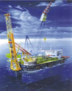
Saipem has developed a J-Lay system which will be installed on their S-7000 SSCV. The J-lay system is of modular design and can be installed and removed by the existing heavy lift cranes. This approach ensures that the vessel will retain its existing heavy lift capability, maximizing the S-7000's functional utilization, Saipem claims.The dynamic positioning system of the vessel will be enhanced. New thrusters will be installed. The power generation plant will be upgraded as will the distribution systems and peripheral system. Overall, the DP thrust will be increased from the current value of 420 tons to 750 tons.
By installing the system on the bow of the vessel, between the cranes, with an outbound tilting tower, it will allow for operations close to platforms to be undertaken such as steel catenary riser installation using a simple handover method.
The following describes in more detail the particulars of theS-7000's J-Lay system, according to information provided by Saipem:
Quadruple joint system
This system is made up of two double joint modules, one quadruple joint module, and one beveling module. Pipe storage occupies the deck around the quadruple joint area. The number and the layout of pipe storage stacks is project dependent.Crawler cranes and conveyors move the pipes from the stacks for end preparation in beveling station module after which conveyors transfer the pipes to the quadruple joint area for welding.
The quadruple joint system is located on two different elevations. On the lower elevation the four pipes, already beveled, are welded together in order to form two double joints (by means of four welding stations). At a fifth station, the non-destructive testing (NDT) is performed. The double joints are then transferred to the deck level where the quadruple joint is produced using four welding stations. The quadruple jointing process is completed in the normal manner by NDT.
Pipe handling
On completion of the joining of the 48-meter quadruple joint, the joint is transferred by means of conveyors to the pipe loader. The loader tilts the pipe about a hinge (placed on the tower), driven by means of two winches.Once in the vertical position (at the same inclination as the tower), a clamp elevator takes the pipe and moves it up to the top of the tower. Here, a clamp system transfers the pipe to the firing line (tower axis) where it is taken by the line up system and is now ready to be welded to the existing pipe string.
J-Lay tower
The tower is installed on the bow of the vessel, between the two heavy lift cranes. The coupling between vessel deck and tower is made by means of two hinges capable of varying the tower inclination from 90° to 110° (from vertical to 20° outboard from the bow). The inclination of the tower is driven by a jacking system installed on an A frame placed on the deck. These structures - tower and A frame - are specifically designed so as to be installed using the S-7000's own heavy lift cranes.The J-lay tower and padeye connection system to the vessel is designed with a future capability upgrade in mind. It has a total load/holding capacity of 2,000 metric tons. The tower has three major components:
- The upper section (about 57 meters long) is a lightweight structure that accommodates the coupling device and the line-up clamps. The structure is designed to support its own weight and the equipment with the pipe string.
- The middle section (about 54 meters long) accommodates the welding station, the three tensioners (including the idle fold-away sheaves for the abandonment and recovery system) and the pipeline roller supports.
- The lower section (about 20 meters long) accommodates the clamps and the NDT and field joint station.
The configuration of the tensioners is such that they will allow in-line installation of large objects such as tees and valves up to 2.5 meters in diameter.
A & R system
The abandonment and recovery system (A&R) is made up of a double capstan winch (electrically driven) with a reel winder and a 4 3/4-in. wire steel rope. The wire rope is driven to the fold-away sheave (placed on the middle part of the tower) and then connected to the pipeline head. The A&R system is accommodated on the main deck in a central position close to the quadruple joint module.One of the sheaves is located on the deck adjacent to the tower, while a further two are located at the top of the middle section of the tower. The A&R system is rated to 550 metric tons maximum pulling force.
Welding, NDT
Initially, the welding system to be used is likely to be the well established Passo GMAW system, which has a significant track record on Saipem/ EMC vessels. The system will be used to weld diameters in the range 10 in. to 32 in., while for smaller diameter pipes, welding will be manual.The NDT and field joint station is located above the friction clamps. The general advantages of this method compared with radiography are well documented, but the absence of internal equipment is particularly important for J-lay application.
Future upgrading
Structurally, the system as designed allows for a pipe holding capacity of 2,000 tons. The main components in a future upgrade to the full 2,000 tons capacity will be the requirement for a new holding system and a new A&R system.In the case of the holding system, it will be possible to use either an upgraded friction clamp or switch to a collar clamp design (a moveable traveling block). Conceptual design has also been developed for an upgraded A&R system.
Productivity issues with respect to welding technology are also under development for future implementation. Saipem currently is developing a one-pass welding system based on electron-beam technology. It is intended that this will eventually replace the Passo system.
The S-7000 is the largest dynamically positioned SSCV in the world. Saipem says the addition of a modular J-Lay system will open up a new chapter in large diameter ultra-deepwater construction.
Copyright 1998 Oil & Gas Journal. All Rights Reserved.


