Per Kristian Forbord, Lars Myklebost, Arne Skeie, Bård Owe Bakken, Gisle Morisbak Lund, Thore Grønvik - Acergy
null
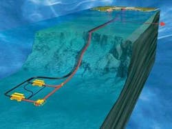
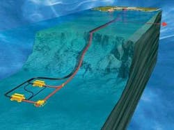
Acergy was awarded the contract to install the MEG pipelines on Ormen Lange. The scope of work was laying and commissioning two 120-km (74.5-mi) long, 6-in. (15.25-cm) pipelines from the gas processing plant onshore at Nyhamna to the Ormen Lange manifold covering water depths to 850 m (2,789 ft). In addition, a 3.6-km (2.2-mi), 6-in. infield pipeline between the two production manifolds was included.
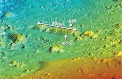
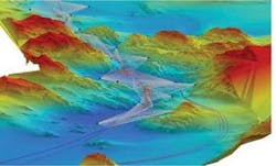
The Ormen Lange gas field is 120 km (74.5 mi) west-northwest of Kristiansund on Norway’s west coast. The field area includes the prehistoric Storegga Slide and water depths from 250 m (820 ft) to 1,200 m (3,837 ft) in the development area. The seabed in the Storegga Slide is irregular with soil varying from very stiff clay with boulders to soft clay.
Installation
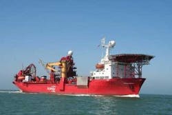
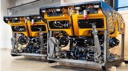
The pipelines were installed by theAcergy Falcon, a dynamically positioned pipelay vessel which can install rigid lines up to 14 in. (35.5 cm) by J-lay in water depths to 1,500 m (4,921 ft). The vessel welds the pipe joints in a firing line onboard and can carry up to 2,000 metric tons (2,205 tons) of pipe joints. The joints also can be resupplied at sea. The vessel also has a Flexible Lay System for flexible flowlines. Flex lines can be stored on deck reels or below decks in a 1,600-metric ton (1,764 ton) capacity powers carousel. The vessel has two work-class ROVs for touch down monitoring and survey.
The 50-year design life of the pipeline required field joint coating. The requirement was a three-layer polypropylene system including an inner layer of fusion bonded epoxy.
Ormen Lange is characterized by uneven seabed with steep slopes in both longitudinal and transverse directions combined with strong currents throughout the water column. The current can increase without warning so the installation vessel must change the system settings at short notice.
The rough seabed bathymetry necessitated an intricate routing consisting of numerous tight lateral curves (down to 500 m [1,640 ft]) connected by short sections of straight pipelay in between. In addition, a very accurate lay tolerance was required to hit pre-laid rock berms and pre-cut trenches. In combination, this required low bottom tension so as not to pull the pipe out of its dedicated lay corridor.
Another outcome from rough terrain is the occurrence of freespan when the pipe is resting on the seabed. A low bottom tension also is required to minimize the length of each freespan.Acergy Falcon can adjust the angle of the lay ramp from shallow to vertical during laying (21º to 90º). This enabled an adjustment of the lay parameters such as bottom tension during laying to align with the requirements for both the shallow and deepwater part. When the vessel performed pipeline down the Storrega Slide (30º slope from 250 to 650 m [820 to 2,133 ft] water depth), the pipe was laid with bottom tensions below 1.5 metric tons (1.7 tons), with a high stylization of the moment capacity in the sag bend. This was to reduce the length of some long freespans and, hence, the seabed intervention cost. This left only small margins for vessel positioning and dynamic impact from weather. Good control over vessel station keeping and dynamic movement was required.
Both static and dynamic analysis was performed for various water depths, seabed terrain, and environmental conditions. Knowledge of the station keeping of the vessel plus its dynamic response in various weather conditions was required for a realistic analysis. This has been obtained for theAcergy Falcon from research on hull models and experience from many years of pipelay in various conditions with various pipe sizes. Current speeds at almost 1 m/s at the surface and 0.5 m/s at the bottom when the water depth was more than 850 m (2,789 ft) created several tons of drag force on the pipe. This has an impact on the configuration of the pipe catenary, especially since the low bottom tension leaves the catenary in a very “slack” shape.
Online monitoring
To meet the routing requirements and not over-stress and damage the pipe, the vessel needed to respond quickly to sudden strong current. Therefore, online monitoring of the catenary was used. Online monitoring consisted of an acoustic Doppler current profiler continuously measuring current direction and speed through the whole water column. Together with the actual vessel position, touch down position, water depth, and departure angle of the pipe, the current profile was an input to a continuous static calculation. The actual static catenary with the current taken into account was monitored always. Tables with vessel position and ramp angle for most possible current scenarios were developed prior to going offshore. These tables and the online monitoring system gave the crew information about which actions to take once the current increased.
During the installation of the Ormen Lange MEG lines, strong current coming in transversely to the lay direction required the vessel to offset as much as 90 m (295 ft) from the lay route and rotate 37° to the laying direction.
The actual residual bottom tension also was captured from the online monitoring. The tension was higher with a current in the lay direction. The residual bottom tension along the whole route from shore to the field was captured for the MEG lines. This was essential for the post-lay trenching.
Laying a pipeline in deepwater with strong current also created another fatigue challenge. The journey each pipe joint needed to travel down the catenary before landing on the seabed combined with rough sea state and strong currents through the water column made the pipeline vulnerable to fatigue. Stops in the pipelay, such as weld repairs, would further add to the fatigue exposure in the catenary. When current is present in the water column, vortex induced vibrations (VIV) can occur. VIV normally is addressed only for the pipeline in operation. Full-scale fatigue testing and extensive fatigue analyses both with and without the presence of VIV were performed prior to the start of offshore operations. The results of these tests (improved S-N curve from F1 to E) were considered in the analysis and methodology. This, in combination with the vessels ability to lay pipe with low bottom tension (slack catenary), and the repair rate of 0.63%, kept the wave induced fatigue to a minimum.
Survey technology
The remains from the Storegga slide limited the routing possibilities. Pre-intervention work such as rock-dumping and excavation was necessary to create installable routes. To limit the pre- and post- intervention, strict lay tolerances were set on parts of the routes. This was in conjunction with low curve radius on the pipeline route to avoid the many large blocks of clay on the seabed. In a large area in the lower part of the slide edge, a thermocline often was observed between the extremely cold water (below 0° C [32° F]) at depth, and warmer water higher up. These thermoclines were known to introduce errors to acoustic ranges, or even completely block acoustic signals.
To meet the installation tolerances, the very latest of survey technology was used. This included:
- Dual head multibeam sensors
- Inertial system
- Long baseline acoustic positioning
- Digital terrain model of the seabed from the prelay survey
- High precision GPS surface positioning.
The new survey sensors had to be mounted on the ROV and integrated with standard spread of survey sensors. The survey crew is essential on theAcergy Falcon as its members control the positioning of the vessel and place the pipe within the lay corridor by adjusting the vessel position. The surveyors also operate the automatic pipelay system (APS). APS controls all the various stations in the firing line and feeds the DP system with data on when and how much to move when a cycle is complete.
The vessel has a Kongsberg HiPAP 500, a Super Short Base Line (SSBL) normally used to calculate the subsea position of the ROV and other equipment relative to the vessel based on acoustic distance and heading. The vessel is positioned by GPS within 0.5 m (1.6 ft) accuracy.
A new development to improve acoustic positioning is to use the actual motion of the ROV. This is called “inertial navigation” and both ROVs were equipped with Kongsberg’s HAIN system. This reduced noise on the acoustic signal to give a more reliable and stable position. Even with the INS system, the SSBL accuracy depends on water depth. When the depth started to go beyond 50 m (164 ft) and the required installation accuracy was less than ± 2.5 m (8 ft), other technology was required to maintain accuracy.
A large number of Compatts had been installed to form many large LBL networks where positioning accuracy within the array was better than 20 cm (8 in.). LBL is acoustic and requires minimum of three ranges between ROV and transponders in known positions and depths to calculate a position. The client decided to use the Sonardyne MR Wideband on parts of the routes. The new generation LBL combines high accuracy, longer range, and faster update compared with EHF, which also was used.
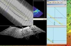
Also, on theAcergy Falcon for the first time was the dual head multibeam system (Kongsberg EM3002). This was developed to map the seabed in detail, but for this project was used as an advanced cross-profiler. The multibeam system gave an instant “3D” view of the seabed which clearly showed the 6-in. diameter pipeline in relation to pre-plowed trenches, other pipelines, boulders, and clay blocks. Together with the seabed information from the pre-lay surveys, the image from the MBE system was used to position the pipeline to keep post-intervention work to a minimum.
Interfacing these new sensors was challenging and required upgrades on the ROVs. The amount of data to go through the ROV umbilical required a fast data link. The systems are sensitive to noise and leave little room for error. For this upgrade, the project team in Stavanger, Norway, was supported by the ROV department in Aberdeen, UK.Acergy Falcon was the first vessel to use the HAIN system.
PLET installation
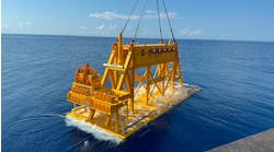
Four pipeline end terminations (PLETs) were installed in 85 ft (26 m) of water. These 15-metric ton (16.5-ton) PLETs were designed by FKS in cooperation with Acergy to optimize the structures for installation from theFalcon.
The selected tie-in system for the MEG pipelines was the CAT-10 system by FKS. The consequence of using this was a comparatively large PLET with a relatively awkward position of center-of-gravity (top heavy). As the 6-in. MEG pipeline was thin wall, this posed a challenge with respect to allowable bending moment during deepwater and harsh environment installation where currents were expected. The solution was a balancing act considering the position of installation padeyes in relation to the center of gravity, weight of pipeline catenary, position of the vessel during installation, and the actual currents.
A static PLET frame was used for the installation. This frame was used on several previous Acergy projects and was refurbished specifically for Ormen Lange PLETs. A 120-ton (109-metric ton) winch was installed inboard of the PLET frame for pipeline recovery, PLET-to-pipeline tie-in operations, and PLET laydown. To support the PLET on the soft seabed, a 7 m x 14 m (23 ft x 46 ft) steel plate was pre-installed in the designated target boxes.
Project challenges
The technical challenges to pipeline installation in the Storegga Slide area included the following:
- Extreme seabed topography combined with non-homogeneous soils requiring seabed intervention
- Steep slope down the slide escarpment for pipelay and intervention
- High current velocities and direction variations through the water column
- Uncertainties as to current velocities, directions, and distribution, particularly around local severe topography
- Tight installation tolerances for pipelines
- Thermocline
- Deepwater
- PLET installation
- Pipelay online monitoring.
