Development to date of the multi-purpose AUVAlistar 3000 by ECA has culminated in a 10-day deepwater pipeline inspection trial for BP America Production Co. in the King field in the Gulf of Mexico. In mid-2006, the Alistar 3000 completed a pre-programmed inspection mission with no physical link to the surface.
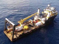
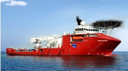
The trials were supported by ECA’s US partner Harvey Lynch Inc. from an Oceaneering vessel hired by BP. The runs included several missions at 1,356 m (4,450 ft) on a 229 mm x 330 mm (9 in. x 13 in.) flowline. The vehicle capabilities were confirmed for the following:
- Accurate repositioning close to seabed after the descent phase
- Keeping an acoustic supervision from the surface throughout the mission
- Validating a sophisticated mission management system
- Finding and “locking” onto a pipeline after a searching phase
- Tracking and closely following a pipeline between 1 and 2 m (3.28 and 6.56 ft) above the pipe enabling recording of high quality video images of the pipeline
- Detecting and carrying out close inspection of an anomaly using dedicated patterns
- Safely being recovered to the surface.
System description
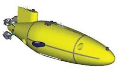
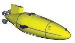
TheAlistar 3000’s main characteristics are a length of 5 m (16 ft), a maximum body diameter of 1.2 m (4 ft), an overall height of 1.5 m (4.9 ft), total weight of 2,100 kg (4,630 lb) including up to 200 kg (441 lb) payload, and an operating depth of 0-3,000 m (0-9,842 ft).
It is equipped with four longitudinal, two lateral and two vertical thrusters. The actuators layout provides maneuverability, especially at zero speed, giving the vehicles the ability to hover. An active ballast system enables the vehicle to operate from 0 to 3,000 m (9,842 ft) without the need to manually adjust the ballasting before launch. Alistar is able to operate at 0 knots while hovering and can achieve a maximum speed of 6 knots through water.
The vehicle has pitch and roll stability due to its mechanical architecture, reducing the energy consumption for stabilizing the vehicle, which is of paramount importance for an AUV.
This cut-away of the AUV shows the removable payload skid front section and bottom section.
A removable lithium ion secondary battery, housed in a pressure hull, offers 25 kW of embarked energy with a maximum recharge time of eight hours. This battery provides 24-hr autonomy at cruise speed. A computer-based battery management system monitors the battery status.
Accurate positioning, tracking, and monitoring are achieved using the following equipment: Navigation sensors such as Inertial Navigation System (INS), Doppler Velocity Log (DVL) and Kalman Filter; high accuracy depth sensor; altimeter; obstacle avoidance system; GPS; and, acoustic localization transponder.
The AUV has several communication systems, including a fiber optic link, a radio Ethernet link and underwater acoustic communications. The fiber optic link is used when the vehicle is onboard the ship to download the mission before launch and to retrieve data at the end of the mission. This link also can be used to get real-time data such as video and sonar images from the vehicle. The radio link is used on surface, to transfer data between the vehicle and the surface ship and to operate the AUV from either the main console or a portable remote console during launch and recovery. The underwater acoustic communication system consists of a bi-directional, low data rate link to monitor and to send orders to the vehicle and a high-rate data link to send video or sonar images to a surface vessel to monitor the quality of the data recorded by the vehicle.
Vehicle safety is provided by a health monitoring system, integrated safety weights, safety beacon, radio and ARGOS beacons, flasher, and water ingress sensors.
Autonomy management
The Autonomy Management System (AMS) of the AUV has to execute a mission, that can be modified in an uncertain environment. Execution must take into account the external factors (a surface ship, a target) with which the AUV may communicate. There are other aspects to consider as well, such as the internal Health Management that is not necessarily coupled to the mission.
For this function, the AMS must manage data coming from sensors (depth meter, sonars, communication receivers) and must generate orders to actuators (propellers, communication transducers) so the mission can be executed.
The AMS has a dual-function structure:
1. “Awareness making” uses sensor data to generate a numerical state of the vehicle and its environment, and some symbolical events (by detection and classification).
2. “Decision making” uses the previously gathered data to generate the desired behavior by means of actuators. Guidance and autopilot are the low-level part of decision making.
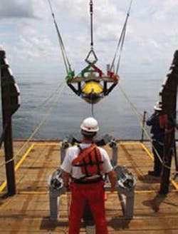
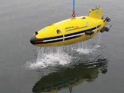
The AUV launch for BP’s Gulf of Mexico tests.
The AMS uses a dual “living” database structure. The “World Model” is ana priori numerical model of the vehicle, the environment, and their interactions. This model is initialized at the beginning of the mission and can be modified during the mission. The “Vehicle Behavior” describes (in coherence with the initial World Model) ideal expected vehicle behavior.
TheAlistar 3000 Mission Management System is part of the overall AMS, which provides the operating team with complete functions for planning, monitoring, and post-processing through its Mission screen and Data Vision screen.
Mission planning
The mission screen offers improved easy-to-use interactive tools to create basic AUV behaviors based on pre-defined models. A mission model is composed of “phases” associated with behaviors and “chaining links” that specify how mission phases are linked. Security parameters also are defined to complete mission data (working area, intended duration of mission, thresholds). Models are managed through a database system to make mission data persistent.
An integrated simulation function permits verification of the coherence and feasibility of the programmed mission.
Mission data can be uploaded to the AUV through Ethernet radio link in the common XML format.
The Data Vision screen shows video/sonar data from AUV cameras, plus navigational parameters, to help the operator manually control the robot to get it into the correct orientation to start autonomous operations. The screen is also used later for recovery at the end of the mission.
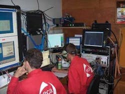
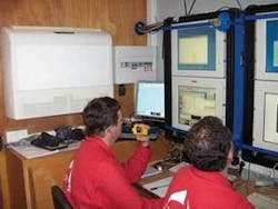
Mission management equipment is carried out onboard an assist vessel.
The mission is monitored using a USBL system and by data received from the AUV through acoustic transmission. Optionally, operations can be supervised by sending single orders to the AUV according to the programmed mission or for security reasons.
Mission post-processing
After downloading the onboard data, recorded payload data are processed and analyzed using manufacturer provided tools. Recorded navigational data can be re-played (Mission screen) synchronized with recorded video/sonar data (Data Vision screen) under the control of the operator in a “Video Player” way. They also can be processed specifically for transfer to an external analysis system.
Distributed software architecture of the system, based on a “publish-subscribe” data server, gives it scalability and AUV behavior enrichment capacities.
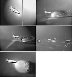
This artist’s rendering illustrates types of missions for theAlistar 3000.
Due to its high stability, maneuverability, and hovering capability,Alistar is a multi-purpose vehicle. However, the system is designed primarily to inspect underwater structures such as pipes, risers, mooring lines, wellheads, manifolds etc. It also provides pipelay assistance by carrying out TDP monitoring. The system can perform various missions such as general site survey, pre- and post-lay survey.
Payloads are installed on skids in two sections of the vehicle, one at the front and the other underneath. The system has been designed for interface with different manufacturer equipment.
Each year, thousands of kilometers of pipelines are inspected with towed fish or ROVs fitted with sonars, video, and magnetic sensors, opening a market for inspection type AUVs.
The difficulty for pipeline inspection with an AUV mainly lies in the fact that as-built reports giving the position of these pipelines are not accurate enough to be able to pre-program a trajectory with waypoints above the pipeline. Video inspection of a pipeline also means the AUV is directly above the pipeline with a tolerance of about 508 mm (20 in.) either side and at about 1 m (3 ft) above it.
The AUV used for performing this type of task requires the vehicle to be very close to the pipe. This means a vehicle with high maneuverability to keep its relative position to the pipe and to avoid a collision with the seabed. TheAlistar is fitted with thrusters to provide several degrees of freedom.
The vehicle also needs to have a specific set of sensors (in addition to the video system used to record the pipe video images) to find the pipe and to follow it even when sections are partially or totally buried.
To develop pipeline inspection for theAlistar 3000, several steps were followed and trials conducted since 2004. The first tests used Alistar 3000. These trials were in July 2004 with the inspection of a 508-mm (20-in.) diameter, 500-m (1,640-ft) long pipe in shallow water in Toulon, France. During these tests, Alistar 3000 was “locked” onto the pipe by the operator. Once locked, the vehicle followed the pipe autonomously, using its acoustic sensor, 1-2 m (3-6 ft) above it, recording video images.
Then, this first version of Autonomous Inspection Capability was transferred toAlistar 3000 while testing various types of sensors that could be used for pipe and underwater inspection. Among the sensors tested were: side scan sonar, multi beam echo-sounder, magnetometer, acoustic profiler, and CP sensors. This assessment phase was concluded in 2004. The selection of a set of acoustic and magnetic sensors was then integrated and tested with Alistar 3000.
The suite of sensors selected together with the algorithms developed enable the vessel to search for the pipeline; automatically detect and ‘lock’ onto the pipe; follow the pipe, detect and inspect CP anodes; approach and inspect a structure with a dedicated pattern; and, record video and sonar images of the pipe.
These capabilities were demonstrated in sea trials in France in 2005 and 2006.
