PART II: This is Part II in a two-part series dealing with multiphase hydraulic submersible pumps, specifically the one used on Texaco's Captain Field. Part I appeared in the September issue.
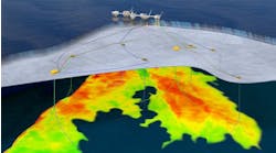
Area B of the Captain Field, located in the UK sector of the North Sea, consists of four discrete oil bearing reservoirs: the Upper Captain Sand (gas cap area), the Upper Captain Sand (eastern extension), the Ross Sand, and the Southern Terrace. To access the reserves associated with Area B, up to 18 wells and additional topsides process facilities would be required to handle the increased oil, water, and gas production rates.
Initial plans were to upgrade the floating, production, storage, offloading (FPSO) process train; however, this was an unattractive option with regard to the loss of production associated with taking the vessel into drydock for modifications. For this reason, it was decided to focus on options that provided the additional processing capacity on a new, fixed structure in order to minimize the operational impact on the FPSO.
A key consideration during front-end engineering for Area B was to select the most appropriate downhole artificial lift method(s), given that only geological interpretation indicated that the Gas Cap area of the Upper Captain Sand (UCS) was known to have a significant free gas cap. For this reason, early consideration was given to employing a combination of electrical submersible pumps (ESP) for the non-gassy reservoirs and hydraulic submersible pumps (HSP) for the Gas Cap area as a means of minimizing water handling requirements in the separators.
The wellheads and separators would be installed on a new combined drilling and production platform. However, analysis indicated that a more economic solution would be provided by using subsea wellheads, tied back to a new process platform (BLP) bridge-linked to the existing wellhead protector platform (WPP) 'A' platform.
The BLP would carry out free water knock-out, gas separation, compression, and export on both the Area A and Area B fluids, prior to sending wet oil across existing in-field lines to the FPSO. Once the key decision to make Area B a remote subsea development had been taken, it became clear that a hybrid HSP/ESP development was impractical. Furthermore, the HSP offered the potential for superior reliability - critical in view of the high intervention costs applying to subsea wells.
The selection of HSPs as the optimum artificial lift method for Area B was subjected to a rigorous internal peer review, where HSPs, ESPs, and gas lift were reviewed as potential alternatives. This review confirmed that HSPs were likely to provide significantly greater production uptime than either of the two other potential alternatives. In addition, the predicted mean-time-to-failure (MTTF) of an HSP was predicted to be significantly higher than for an ESP, primarily due to the avoidance of gas locking. Both these aspects contributed to significantly lower predicted operating costs for the HSP option over the life of field.
Area B well design
In order to capitalize on prior experience, the Area B well completion design employs many of the features that were successfully used on C13 trial well. A significant number of revisions were made in order to meet the higher production rates required, as well as deal with a more variable range of producing gas-oil ratio (GOR) than originally expected. This applied not only to the aspects directly related to HSP system equipment, but also to the lower completion design.
Due to the highly unconsolidated nature of the Captain sands, sand control is essential to prevent excessive sand production, which would not only lead to process difficulties, but would result in abrasive wear to any type of downhole pumping system. Gravel packing is thought to be particularly appropriate to Area B where gas production and pressure depletion are certain to occur during the "blowdown" phase of production from the gas cap area.
A key requirement for the Area B development was to minimize the volume of HSP power water that the separators would have to handle, as this would impact vessel size, weight, and cost. In addition, in order to ensure acceptable offtake rates for the Area B reservoirs, a net production rate of up to 18,500 b/d of oil at solution GOR was specified in the HSP design basis.
A very wide range of producing GORs was predicted for the Gas Cap region. Field and flow loop testing had demonstrated the excellent gas handling of the pump under transient gas slugging conditions; however, at the very high values of GOR predicted for Area B, it would not be possible to continue operation of the HSP without compromising the MTTF. Under these extreme conditions, it would not be possible to maintain sufficient pump differential pressure to ensure satisfactory lubrication of the pump bearings.
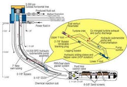
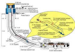
The HSP installation in the Area B wells incorporates a logging bypass system with the pump located between upper and lower 'Y' blocks and a parallel string of 2 7/8-in. bypass tubing providing coiled tubing or tractor wireline access to the reservoir for pipeline termination (PLT) surveys or other interventions.
Early transient hydraulic studies on optimum setting depth for HSPs had favored locating the pumps as deep and as close as possible to the reservoir interval to minimize the size of any gas slugs that entered the producing interval due to coning. This was seen as beneficial in terms of flow stability under gassy conditions. It also improves the overall efficiency of the pump system by minimizing the average gas fraction of the fluids entering the pump. Deep setting the pumps at an inclination of greater than 80 degrees to the vertical would introduce certain penalties such as no slickline operations, necessitate the use of 11 3/4-in. casing and increase operational risks.
Setting the pumps at an inclination of no greater than 60 degrees to vertical would address all the cited issues. However, in view of the earlier transient studies, developing confidence was necessary to prevent compromise of well operability or the development of unacceptable HSP efficiencies. To the heel point of each well in Area B, tailpipes vary in length from 1,500 ft to 4,700 ft.
Downhole monitoring
Permanently installed downhole monitoring systems in Area A wells have proved to be an extremely valuable tools with regard to pump condition monitoring and protection, while also facilitating real time reservoir monitoring through the measurement of pump inlet pressure. In addition, downhole flow measurement can be used to improve the accuracy of production allocation, which facilitates effective reservoir management.
A significant difference for the Area B downhole monitoring system design is in the telemetry system used. This enables many more sensors to be "daisy-chained" onto a single signal cable than previously possible (up to 255), with a reduced likelihood of "data-collisions" which have on occasion led to data drop-outs.
The viscosity of Captain crude is higher than that of any other currently being produced in the UKCS, as high as 137 cp in the Lower Captain Sand. Although the viscosity of the oil being extracted by the Area B wells is somewhat lower at 88 cp maximum, the crude has a tendency to form tight emulsions when mixed with water, as occurs within the high-shear environment of downhole pumping. These emulsions may have a viscosity up to four times as high as that of the oil itself, and this behavior has to be allowed for in the design of the downhole completion, the subsea infrastructure, and topsides process equipment.
To minimize the potentially detrimental effects of high emulsion viscosity on pump performance and frictional pressure losses in tubing and subsea lines, the Area B completions utilize the emulsion control practices successfully used in the Area A ESP wells. Demulsifier is injected downhole through check valves into the flow upstream of the pump inlet.
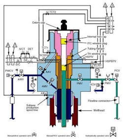
The Area B subsea wells follow established Captain A practice in that they are of the horizontal or spool type design with the production master and wing valves located on a branch connection on side of the tree rather being concentric with the production tubing.
Subsea infrastructure
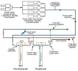
The unitized template manifold (UTM) incorporates all the necessary facilities required to supply power water from a manifold to each individual wellhead at the desired rate. The UTM also receives the produced fluids and allows routing of the produced fluids into either of two production manifolds or a single test manifold. Two segregated production manifolds are provided following transient simulation studies, which suggested that segregation of high GOR and low GOR production may be necessary to ensure acceptable slug flow characteristics and process stability.
The phased startup of Area B means that power water demand will steadily grow with the number of commissioned wells. The topside power water pumps supplied for the BLP were sized to provide sufficient power water for 10 wells operating at the maximum design well flow rate, plus a 10% margin. Four electric motor-driven main power water pumpsets were provided in a 3 x 33% + 33% spare configuration
It was recognized at an early stage that accurate power water measurement on an individual well basis would be essential for a number of reasons, including:
- Reservoir/well monitoring, to allow clear differentiation between water production (from the reservoir) and power water
- Production optimization, by ensuring that the desired distribution of power water is actually being achieved, especially important in later field life when power water is constrained
- Pump performance monitoring, to allow any trends in pump or turbine efficiency to be tracked with time.
Although the UTM is only some 4.8 km from the receiving facilities at the BLP, there is the potential for the relatively cold, viscous Captain oil to cool significantly on shut-in and increase dramatically the pressure required for restart of export from the wellheads. Therefore, the power water system has been designed to permit crossover of power water from the subsea power water manifold into the main low gas, subsea production manifold.
This crossover line allows power water to be used to flush the production pipeline and assist system startup. Water can be circulated to heat the production piping system and to maintain the water cut of the fluids in the low gas production line during the early production period. The flushing flow rate is controlled by means of a crossover choke valve.
Well B1 verification
The first Area B well completion was installed in December 2000 in well B1. A short verification test of the pumpset was carried out to confirm the correct operation of the HSP and downhole monitoring systems prior to the semisubmersible carrying out final subsea hookup operations and moving off location. Although the test was limited in duration to avoid producing hydrocarbons to surface, sufficient data was acquired to confirm normal pump operation had been achieved.
Following final completion and well commissioning operations, the well was put on production using power fluid supplied from the power water charge pumps on the BLP. Well cleanup was largely uneventful, although some fluctuations in flow rate were experienced as a function initially of fluid viscosity effects on the pump, then latterly in response to varying wellhead pressure with the pump speed indicating more uniform produced fluid properties. No indications of free gas production were evident at this time.
When normal production of the well through the BLP production facilities commenced in early January 2001, the downhole measurements confirmed a gradual increase in producing GOR from solution-GOR (130 scf/stb) to around 250 scf/stb. Following an oil production rate reduction from 10,000 b/d to 5,000 b/d, the degree of gas coning also reduced, with the producing GOR dropping to around 160 scf/stb. The pump speed and pressure trends from this early production period were developed.
Conclusions
The successful field trial and subsequent large-scale deployment of the multiphase HSP has demonstrated that a controlled risk approach, through phased development, can be used effectively in proving new variant technologies on operating fields. In the particular case of the multiphase HSP, the program has led to the development of downhole pumps that can be used for extended operation at elevated gas void fractions (GVFs) to 75%.
The unique hydraulic design employed within the pump end, coupled with the inherent variable speed of the turbine drive, has also demonstrated the capacity to handle slugging gas/liquid flows and avoid gas locking over a wide range. Exploration of the multiphase stage designs has shown that careful consideration must be given to the balance to be struck between gas handling capacity and head generation when sizing equipment.
Where extremely high GOR conditions apply, it may be preferable to bypass the lift system altogether, and in such cases, this capability should be included in the functional specification for the completion. For future developments, further investigation of pump-based solutions to the high GOR/low head scenario may be justified, provided this does not result in mechanical over-complexity of the pump unit, which may be detrimental to the goal of high reliability.
The field trial and subsequent Area B deployment has shown how hydraulic lift systems incorporating HSPs can be engineered for flexibility and with flow assurance contingencies through proper consideration of the system infrastructure. The use of downhole monitoring systems to provide real-time data has played a key role in the understanding of well and pumpset performance characteristics on the way to a full evaluation and verification of the new technology.
Over the next few years, and with the phased deployment of the remainder of the Area B HSPs, the main aim will be to verify the longer-term reliability of the system in gassy heavy oil, high rate production environments, as well as to refine the modeling of in-situ pump performance as an aid to performance prediction and power water optimization.
Acknowledgement
Weir Pumps Ltd. and Texaco granted permission to publish this work. Angus Grant, Tom McConnell, John Dallas, Ronnie Graham, and Alex Lindsay of Weir, as well as Alan Morrison, Graeme Rae, and Sam Kashou of Texaco helped bring this project to a successful conclusion. The late Mike Ryall (Weir) layed the foundation for the development of this technology, and David Cohen (ex-Texaco) helped bring the trial to fruition. Expro North Sea Ltd. helped develop the downhole monitoring system, and Phoenix Petroleum Services Ltd. and P.E.S. Ltd., a Halliburton company, assisted in Area A and Area B completion equipment, respectively.
Reference
Cohen, D., Dallas, J., Knight, F., Woerheide, E., "Development of a Gas Handling Hydraulic Submersible Pump and Planning a Field Trial, Captain Field", OTC 8511, OTC, Houston, Texas, May 1997.
