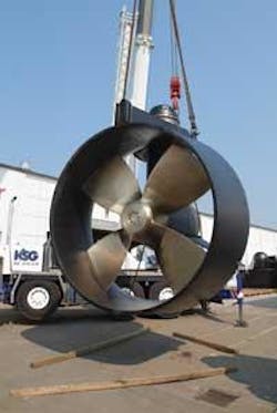
Operating in diverse and extreme offshore conditions requires structures to be dynamically positioned and to have their own propulsive power. Several of the new semisubmersible technological innovations will be dynamically positioned by the Flowserve Pleuger thruster.
New tilted-axis design
By combining application expertise with the latest in design principles, Flowserve Pleuger has developed an underwater-mountable, L-drive and fixed-pitch thruster line for offshore applications. The WFSD-type thruster with tilted-axis propeller is designed for optimum net thrust output and maintainability, the company says.
The company lists several features incorporated to deliver maximum performance, long service life, and ease of installation and maintenance:
- A 7° tilted-shaft propeller to reduce thruster-hull and thruster-thruster interactions
- Easy under-water mounting and dismantling operations
- A duplex-thrust bearing allowing windmilling at any speed
- An automatic pressure compensation system for adopting differential pressure to draft during transit or operation.
The newly-designed thrusters can be customized with up to 5-m (16-ft) propeller diameter, and for greater than 4,000 kW input power with a fixed-pitch propeller (FPP).
The thrusters are designed for DP vessels with significant draft variations such as semisubmersible rigs. Other applications include those for FPSOs, drillships, crane vessels, and pipelay vessels.
Construction principle
The downward tilt of the propeller axis is achieved by using a special gear. This avoids the boundary attachment (Coanda Effect), thus avoiding severe thrust deductions resulting in higher net thrust, the company says.
Flowserve Pleuger thruster schematic drawing.
A 97° cyclo-palloid spiral bevel gear is incorporated in the design. This gear type has a uniform tooth depth over the entire tooth width that follows the path of the epicycloids. The gearwheel is in between the propeller and pinion placement. This ensures optimum contact pattern, especially with increasing thrust, according to Flowserve.
These gears are produced with the HPG method. The pinion and gear are rough machined, case hardened, and then finished with carbide tooling. All transmission parts (i.e. gearwheels and bearings) are designed with industry-leading service ratings and safety factors. The design loading is based on continuous running in DP conditions.
The thruster’s nozzle is based on approved types that are optimized for maximizing the net thrust in bollard conditions. The nozzle and thruster are identically tilted and co-axial, allowing for reduced clearance. According to Flowserve, this results in better performance in comparison to combining the tilted nozzle with the horizontal propeller axis. The propeller wash is directed away from the hull by the tilted-axis, avoiding the Coanda Effect. The result is a higher net thrust.
Thrust deduction in DP-capability calculations may be assumed to be zero. The additional thrust results in an improved station-keeping capability plot within higher operational limits.
With the slightly downward-directed propeller wash, the thruster- to-thruster interaction can be reduced significantly, Flowserve says. Forbidden angles are minimized and the vessel concept may be optimized with different constraints.
Seal system
Flowserve uses as a standard four lip, viton-on-ceramic seal arrangement on the propeller shaft. The differential pressure is maintained as constant by an automatic pressure compensating system, ensuring maximum life on the seal lips. The seal is on the outside, protected by a Flowserve Pleuger-designed rope guard and net cutter. The multi-lip sealing at the azimuthing coulomb is bolted to the foundation in the azimuth gear. Each chamber between the sealing rings is accessible by two check lines.
Lubrication system
The propeller gearbox of the Pleuger thruster is completely flooded with oil. For optimum operating condition of the seal system, the gear oil pressure is kept above the outside water pressure by an automatic differential pressure compensating system at all drafts. In the vertical high oil pipe, the outside pressure at each thruster is measured, and the oil level is kept at corresponding levels to secure a constant static differential pressure.
Latest solid modeling design tools are used.
As another design quality consideration, the gear housing suction pipe is located at the lowest point of the housing. This will help directly identify an unlikely increase in water content. Water content in the gear oil may be measured during operation, and the oil may be separated from the water with an optional separator.
This construction principle allows for installing and removing of the outboard part of the thruster without drydocking the vessel, Flowserve says. For maintenance and repair purposes, the thruster can be replaced even when the vessel is in the open ocean.
The thruster is delivered with an outer- and inner-cover for the underwater installation. The outer-cover seals the outboard part and the inner-cover seals the installation opening of the vessel.
With two extended rope fixings, the outboard thruster part can be pulled into position and hydraulically locked. No mounting force is required from the ropes. The inner and outer covers are then removed, and the thruster is mechanically fixed and the drive shaft is installed. As an additional safety and design consideration, a buoyancy neutral cover is supplied for maintenance work in the wet part of the thruster base structure.
Application
ENSCO selected a Flowserve Pleuger thruster for its new design of theENSCO 8500. The current construction of the rig at Keppel Fels in Singapore uses eight Pleuger WFSD 340 azimuthing, detachable, L-type thrusters with fixed-pitch propeller. Flowserve Hamburg will supply 16 more thrusters for two similar ENSCO rigs under construction.
Also, theDSS 38 for Brazilian operator QGP, which is under construction at the same shipyard in Singapore, is another example of a Flowserve Pleuger propelled semisubmersible rig.


