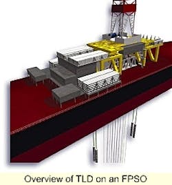
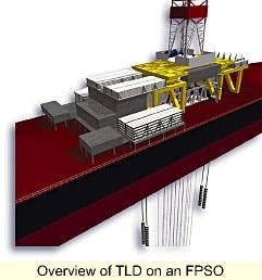
Overview of TLD on an FPSO
Remote oil and gas theaters around the world, including West Africa, offer ideal applications for a new floating pro duction, storage, and offloading vessel that incorporates an independent tension ing deck for dry trees and drilling operations.
The design, developed and unveiled by Single Buoy Moorings Offshore Systems at the Deep Offshore Technology Conference (DOT'99) in Stavanger, Norway, features a Tension Leg Deck (TLD) which allows simultaneous drilling, production, and workover operating in remote, deepwater fields.
The combined FPSO-TLD system is designed to allow early production of some of the wells on a field while others are still being drilled. The TLD, located above the waterline in the moonpool, supports the BOP stack and dry pro duction trees, providing easy access.
Single Buoy Moorings (SBM) designed the system for water depths up to 2,500 meters, but state there are no depth limits. The concept has passed model tests and preliminary designs show the FPSO with TLD will be large enough to support all necessary drilling and production equipment. Approval In Principle (AIP) of the concept has been obtained from DNV, according to SBM Manager of Corporate R&D Jack Pollack.
Early production is becoming a major driver in the high-dollar deepwater market. With heavy up-front costs, operators are looking for a fast return on investment, which means early production. Rather than drilling additional wells with a floater while absorbing the cost of hooking up and operating an FPSO for early field development, the floating production, drilling, storage and offloading (FPDSO) system allows one vessel to perform all functions. This would give operators much-needed early production without interfering with drilling and lump all the costs into one vessel.
West Africa, beyond
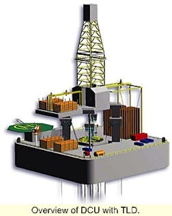
Overview of DCU with TLD.
The initial design is for a spread-moored FPDSO with dry trees supported on a TLD, with application in a West African deepwater environment. However, the system can be adapted to any large or remote deepwater field with high drilling and well maintenance requirements. The idea is to provide stand-alone field development, such as one gets with an FPSO, but with the added benefit of both production and drilling using dry trees.
Due to the West Africa desired storage capacity of over 2 MMBBLS, the design would be built into a standard Ultra-Large Crude Carrier (ULCC), which would then incorporate the unique TLD, to be located in the moonpool of the vessel. Drilling facilities will be mounted on the FPDSO above the moonpool. While a VLCC would be the smallest practical application of this design, SBM has looked at designs incorporating 12 to 20 wells on one TLD. Should more wells be desired a larger hull can be designed to accommodate a second TLD.
A conventional wellhead will be located at the seabed for each well location to provide a landing point for downhole casing strings, tubing suspension, and tieback for the production risers. The FPDSO will be a spread moored system with drilling, processing, oil storage, export, and accommodation facilities.
Tension leg deck
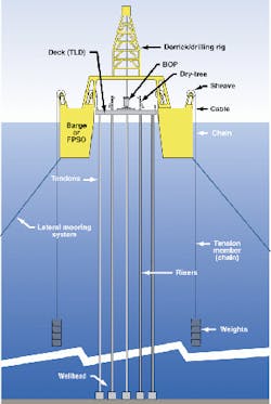
The heart of the system is the TLD. It consists of a deck, BOP, trees, and production and gas injection headers. Attaching the TLD to the seabed are four tendons, one for each corner of the deck. These are piled into the seabed. Attached to the top of the deck above the piled corners are groups of four passive tensioning cables. The cables are routed via pulleys across the hull and back down to chains, terminating at weights some distance below the FPDSO hull.
The TLD works on a similar principle to the familiar tension leg platform (TLP) design. The TLD uses proven TLP production and drilling components including the trees, BOP and risers. The main difference is that the TLD achieves tension using weights rather than buoyancy. The tendons are used to secure the heave-restrained TLD. This allows direct connection of risers between the wellheads located on the seabed and the dry trees on the deck.
The TLD, in the moonpool of the vessel, is passively positioned horizontally and vertically by the tensioning system. The vertical position of the deck is maintained well above the sea level to keep the production trees dry and to provide a safe working area. The system is designed so that the deck will not be immersed, even in the "survival condition." The TLD tendon loads and load variations are less than those on a TLP because the tendons do not have to control the motion of a buoyant hull, just the motion of the weights. The passive tensioning system allows the FPDSO to heave vertically, pitch, and roll with respect to the TLD, but limits the relative horizontal movement between the deck and the vessel. The only structural link between the floating hull and the TLD are the tensioning cables that pass from the deck upward to the FPDSO supported sheaves. Horizontal and yaw excursions of the FPDSO and TLD are kept in check by a conventional lateral spread mooring system anchoring the FPDSO. During the drilling phase, winching the lateral mooring lines make it possible to adjust the FPDSO and TLD position with respect to the wellheads.
The FPDSO will support a skiddable drilling floor with derrick, which is positioned over the TLD and moonpool on a substructure supported by four columns. "The derrick is carried on this substructure," said Pollack. "as the TLD system is configured to carry only equipment that must be heave restrained. Other equipment is much cheaper to support on the FPDSO where it does not have to be compensated by TLD weight."
The clearance between the TLD and the moonpool is a minimum of 2.5 meters in all directions. On the deck the dry trees are arranged in a two by six array. The BOP stack is located on the same level as the trees to minimize the height of the drilling substructure. The BOP, with the marine-drilling riser parking slot, is located in the center of the TLD. The trees are spaced 4.5 meters apart on the deck longitudinally, and are 8 meters apart laterally. On the seabed, the well and tendon slots are arranged in a similar, but larger, pattern as they are flared outwards to increase their clearance at the seabed. The separation on the seabed is 8 meters longitudinally and 12 meters laterally, but this can be changed to suit.
TLD tensioning system
Detailed sketch of the TLD system.
The TLD is held in place by four, air-filled tendons with an ID of 10.75 in. and a wall thickness of 15.1 mm. Though smaller than traditional TLP tendons, the design is similar, as are the top and bottom connections. The normal tension measured at the top of each tendon will be 150 tons. The system is made up of cable, chain, sheaves, and weights supported from the FPDSO. The tensioning system is connected to both ends of the TLD and each connection consists of four cables running over sheaves to a balance system.
The balance system connects the two chains (one of the chains is redundant) to the weights. The weights will be suspended about 100 meters below the surface. This depth protects the weights from wave action and dampens any pendulum action. The equal load distribution of the weight on the four cables and two chains is accomplished by the balance system. This system equalizes the loads and can be adjusted to free up any one of the cables if changeout is necessary. A double winch system, installed on the deck of the FPDSO, will be used to install the weights. These weights are doughnut-shaped and placed around the weight support chains. The chains act as guides during the installation of the weights. When all 12 risers are installed, the total applied tension from the system is 4,400 tons. To accommodate such a load on the FPSO hull Pollack said it looks for a vessel with center tanks and two longitudinal bulkheads. With the moonpool placed in one of the center tanks there will be extensive strengthening of the midships area similar to the work done when fitting an existing hull with a turret system.
TLD drilling
Drilling will begin with the outside wells and move toward the center of the TLD. The derrick will be skidded on the FPDSO substructure to a position above the BOP stack in the center of the TLD. Drilling the outside wells first avoids the need to move the drilling riser past production risers, thus eliminating in-between riser movements. This drilling pattern avoids the need for any producing well to be shut in thus maximizing their production. The wells will be completed using the production riser and the tree located in the appropriate tree slot with the drilling derrick skidded above the slot.
During completion operations, the drilling riser wellhead connection will be assisted by a remotely operated vehicle to a dummy wellhead connector located at the center of the subsea wellhead pattern. This procedure ensures there is no interference between different risers and operations.
The drilling riser can be pulled for maintenance or at the end of the drilling program. For intervention and workover programs, the drilling riser can be reinstalled on a particular well slot by the skiddable drilling derrick. The BOP stack can be reinstalled by a BOP handling system.
Regardless of seastate and weather conditions, the production and drilling riser will remain connected between the wellhead and the deck. The casing or drillstring can be disconnected from the derrick to avoid severe stresses in high seas. In such a situation, the drillstring, or casing, will be hung off inside the blowout preventer for easy recovery. Relative motions between the FPDSO and the TLD are absorbed in two ways:
- A telescoping joint absorbs heave. It will be installed between the rotary table at the drill floor level and above the BOP on the TLD.
- Flexjoints accommodate angular motions from horizontal movement, and will be located at the top and bottom of the telescoping joint.
The production, test, and gas injection headers are located inside the TLD deck on the outboard side of the trees. The fluids are transferred between the deck and the FPDSO using flexible jumpers.
For drilling, Pollack has stated the FPDSO has a similar drilling efficiency as a MODU. This is possible because the TLD supports the dry BOP. If weather conditions caused the suspension of drilling or tripping of casing, the drillstring or casing could quickly be hung off in the BOP, meaning operations could resume quickly. While the price tag on the FPDSO is certainly higher than a conventional MODU, this larger vessel includes storage, process andthe TLD production deck. In addition this vessel will eliminate the need for a MODU over the life of the field.
FPDSO installation
The mooring system of the FPDSO will be installed in a similar way to a conventional FPSO installation. The anchor points and mooring leg components will be installed prior to the vessel's arrival in the field. The FPDSO and TLD anchor piles and any pre-drilled wells are also pre-installed. For the FPDSO, tendon and riser offshore installation can be carried out up to a 3-meter sign wave and current velocity of 0.25 meters/sec. These conditions correspond to the 75% non-exceedance value.
The first step in installation is predrilling any wells, installing the tendon piles, and deploying the spread mooring legs. Once this is accomplished, the FPDSO mooring legs are hooked up, and then the tendons are deployed and latched. Finally, the weight is transferred to the tendons. It is the tendon deployment, latching, and weight transfer that distinguish this installation from that of a standard FPSO.
Deployment
During the tendon deployment, the TLD deck will be locked in its upper-most position. All four tendons will be deployed using the drilling derrick in the same manner casing would be run. When the bottom of the tendon is just above the seabed, it will be crosshauled from the central moonpool, under the deck, to its slot in the corner of the TLD. Once the tendon is drawn up through the deck, gripper-type tensioners and pup joints will be applied to adjust the length of the tendon. This process will be performed in the same manner for all four tendons.
Before releasing the TLD from its locked position, the first set of weights is installed to offset most of the load of the deck with the tendons during lowering. Before release, the deck is connected to the heave compensated drillstring of the drilling derrick. This allows for control of the vertical position of the TLD from the drilling derrick.
Using the lateral mooring system, the FPDSO is positioned to bring the tendon anchor latches above their receptacles on the seabed piles. Once this is done, a remotely operated vehicle will be used to orient the tendons for stab-in one at a time.
To facilitate the stab-in, the stabbing guides on the seabed piles will have funnels at different heights. Once all the tendons are sequentially placed in the guides, the deck will be lowered until the Roto latch connectors engage. The deck will then be lifted putting the tendons into tension, using the derrick heave compensator. Upon completion of the tendon hookup, more weight will be added and the load transferred from the derrick to the TLD's passive weight heave compensation system. The deck is now ready to receive production risers.
Pollack believes an FPDSO - TLD could be put into service within 28 months of receiving the order from an operator.
