Thomas Dujmovich
Armando Gallegos
ConocoPhillips
Specialty Products Inc.
Over the past 25 years, drag reducers (also called flow improvers) have evolved from the original “gel-like” products to suspension products. Flow improvers were initially limited to conventional applications in the pipeline industry. Offshore asset operators generally think of chemicals to control corrosion, scale, wax, and other common asset-based problems, but not specifically of a product to improve throughput. Currently, a growing number of offshore operators are using drag-reducer technology in various worldwide locations.
While the phenomenon of drag reduction was first observed more than 60 years ago, it wasn’t until 1979 that drag reduction technology was developed enough to be used on a commercial scale on the Trans-Alaska Pipeline.
Initially, the pipeline industry believed only in conventional mechanical expansion techniques. It took diligent work to educate the industry about the capabilities of flow improvers.
Successfully used offshore in the North Sea since 1986, flow improvers can address throughput problems, drive production improvements, and realize cost savings. ConocoPhillips Specialty Products Inc.’s (CSPI) flow improvers are currently injected into more than 12 MMbbl of hydrocarbons daily in pipelines throughout the world, including offshore applications. In some cases, daily throughput has been doubled, resulting in significant profitability improvements for customers.
How does it work?
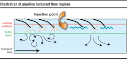
Turbulent pipeline flow consists of three regions across the pipe diameter: the laminar sublayer, the buffer region, and the turbulent core (see Figure 1). Fluid near the pipe wall (the laminar sublayer) tries to stay stationary while fluid in the center region of the pipe (the turbulent core) is moving quickly. This large difference in fluid velocity between the laminar sublayer and the turbulent core causes turbulent bursts to occur in the buffer region. Turbulent bursts propagate and form turbulent eddies, which cause inefficiencies in the hydraulic energy that drives the fluid down the pipeline.
Drag-reducing polymers are long-chain, ultra-high molecular weight polymers. Typical molecular weights for drag-reducing polymers range from 1 to 10 million, with higher molecular weight polymers giving better drag reduction performance. With only parts-per-million levels in the pipeline fluid, drag-reducing polymers suppress the formation of turbulent bursts in the buffer region and thus suppress the formation and propagation of turbulent eddies. This causes the hydraulic energy to be more focused on moving the fluid down the pipeline rather than in a chaotic, random motion.
The net result of using a drag-reducing polymer in turbulent flow is a decrease in the frictional pressure drop in the pipeline. Turbulence and the resulting frictional pressure drop have been shown to be reduced by as much as 70% with drag-reducing polymers.
Drag reduction is defined as the difference in frictional pressure drop along a segment of pipeline comparing untreated fluid and fluid containing drag reducer at a constant flow rate. It can be calculated using Equation 1, where DPf,untreated is the frictional pressure drop in the pipeline with no drag reducer present, and DPf,treated is the frictional pressure drop in the pipeline with drag reducer present. Equation 1 assumes the flow rate is constant.
Drag reducers are used in both oil and water flow applications. Although other drag-reducing polymers are used, oil drag reducers are typically ultra-high molecular weight poly (alpha-olefins), while water soluble drag reducers are typically polyacrylamide polymers.
For two-phase and multiphase slug or bubble flow applications, the continuous liquid phase is the phase which can be drag-reduced. For example, a water content greater than 50 volume percent in the liquid phase makes a water-continuous phase and thus requires a water soluble drag reducer as opposed to a hydrocarbon soluble drag reducer. Water soluble drag reducers are often used in water flooding operations, high water-cut production lines, spent water disposal, and transport of oily water.
Recently, the use of flow improvers has been taken a step further into the offshore environment and multiphase applications. Flow improvers can be used to manage and increase production, significantly lower discharge pressure, and in some instances, change the flow regime, and improve operations.
Cases in point
A 10-in. line experienced on-and-off packed conditions that prevented the operator from maximizing field operations. Use of LiquidPower Flow Improver enabled the instantaneous peak flow to be increased by 6% without reaching a packed line condition. If additional flow had been available, the flow could have been increased by a higher percentage.
Real-time data showed an immediate pressure drop in the pipeline after line-fill at each tested concentration of flow improver and an immediate increase in the export capacity of the pipeline. The crude treater level control valve responded as expected by going to a lower percentage opening, so that it could maintain crude treater level. The export flow rate was higher than the incoming flow rate to the platform, but the level control responded well with appropriate control.
Single-phase application
A crude oil pipeline from the platform to the terminal was tested with flow improver to determine the effectiveness of increased throughput. Before injection, the average throughput was limited by pipeline constraints to 18,200 b/d of oil. This rate was achieved with a discharge pressure of 250 to 255 psig on the platform and use of two pumps. After the flow improver was injected at different concentrations, the choke settings of respective wells were increased from 14% to 32% and from 38% to 44%.
The maximum flow achieved using flow improver was 23,160 b/d of oil. The maximum flow was achieved with significantly lower discharge pressure of 220 to 230 psi on the platform with the utilization of two pumps. More crude oil was pumped through the line than could be produced; therefore, surge tank levels dropped continuously until one export pump needed to be shut down to reduce line throughput. The concentration was lowered to optimize the application, and the choke setting was adjusted on particular wells. The results proved that flow improvers are a cost effective technique to increase the pipeline throughput.
A multiphase pipeline transported approximately 7,000 b/d between systems that are 3.5 miles apart with a gas-to-oil ratio of approximately 1,400 cf/bbl. Flow improvers were tested to help stabilize the system operation. The intent was to reduce pipeline slugging and thereby increase production capabilities.
The operator expressed concerns because of unstable operation at the pipeline and separator. Wells were choked on the pipeline to control flow. Quantitative predictions were not completed because of the variable conditions associated with multiphase systems.
Utilization of field data compiled from the system indicated it was in the “slug flow” regime. The drag reduction improvement of 20% to 21% was achieved almost immediately with the use of flow improvers, which equated to a production increase of 17%. Additional wells were then brought online, and slugging was stabilized with the separator operation significantly improved.
Variable basic sediment
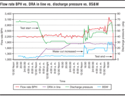
LiquidPower Flow Improver performance was evaluated under different basic sediments and water (BS&W) concentrations to determine the maximum capacity of the pipeline with higher oil and water production.
Increased field production was expected with new wells coming online in the near future. Production was transported to shore via a 16-in. pipeline.
Maximum water production was treated on the platform; however, additional water that was produced was pumped with the crude and later separated and treated onshore. The operator’s objective was to increase oil production, but it was limited by water treatment capabilities. If oil production was increased, water production would also increase. The baseline data indicated that the BS&W in the line ranged from 3% to 6%, and the discharge pressure was 66 psig with two pumps being utilized.
Application of flow improver dropped the pressure from 66 psig to 26-28 psig. As additional flow was brought on, the BS&W increased to 19% with a discharge pressure of 48 psig and then increased to 30% with a discharge pressure of 64 psig. Ultimately, the throughput could be increased from 53,000 b/d of oil to as much as 80,000 b/d of oil with the use of LiquidPower Flow Improvers (Figure 2).
The use of flow improvers can be an effective mechanism to increase production and/or control pressure in many different offshore environments. Traditionally used in single-phase (oil or water systems) and two-phase applications (oil/water systems), the use of flow improver in the upstream arena has expanded to include multiphase applications (oil/water/gas), as well as those with variable BS&W in “crude” applications. Water-soluble applications have successfully utilized flow improvers for water injection and water flood opportunities in an offshore environment.
As the utilization of FPSO systems and floating storage and offloading (FSO) systems increase, CSPI’s flow improver technology can improve the efficiency of offshore hydrocarbon movements and result in improved profitability and productivity for the asset owners.•
Portions of this paper were presented at the 2005 Offshore West Africa Conference and Exhibition.


