JP Chia
Trelleborg Offshore and Construction
The oil and gas industry is known for its constant rate of innovation. It pushes the limits of subsea exploration as deepwater fields and wells are drilled even deeper and located further offshore. So it is no surprise that a new-generation oil platform has been designed. The first of its kind, the Buoyant Tower, which currently sits offshore Peru in the Pacific Ocean, may well revolutionize exploration and production around the world.
New-generation design
Designed to reduce the overall time from offshore exploration to production, this new concept facilitates the fabrication and installation of a drilling and production platform, reduces project times and costs, and provides the flexibility to re-use and relocate the Buoyant Tower anywhere in the world.
Comprising four cylindrical tubes with one central suction pile, each cell measures 8.4 m (28 ft) in diameter and 60 m (197 ft) in length. The central suction pile, integral to the full structure, attaches the structure to the seabed. On top of the 2,500-ton Buoyant Tower hull sits a 1,500-ton platform where the production drilling is carried out. Suitable for water depths between 50 and 280 m (165 and 920 ft), it can be used in any type of field with any variation of reservoir characteristics – oil, gas, or a combination – and the drilling can be modularized to adapt to the needs of the operation.
The tower is designed on existing cell spar technology. Due to the simplicity of the cellular components of the hull, it falls in the category of a "compliant structure" – one that accommodates the dynamic forces through flexibility instead of resisting the loads rigidly, thereby limiting the internal dynamic loads – and is less expensive than fixed platform alternatives. The system is well suited for regions with seismic activity, better than a traditional fixed platform.
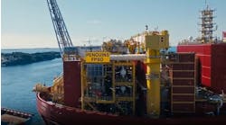
The topsides and fabricated tower of a production platform – which can vary dramatically in weight, from less than 1,000 tons to more than 40,000 tons – are first loaded onto a heavy vessel for transportation to its offshore installation location. The vessel then submerges to allow the tower to float off, while the topsides remains on-board supported by a truss system. Once the tower is upright, it is towed close to its final destination. The critical float-over operation, which involves placing the topsides over the tower to connect the two together, can then begin.
An important aspect of the design is to help dampen the loads while performing the float-over. The crucial challenge being to transfer the load from the topsides to the tower mating points in a controlled manner without causing damage to either structure.
Traditionally the topsides is lifted on to the tower or substructure by an offshore heavy lifting crane. However, the rates for hiring these can be very high. Leg mating units (LMUs) and deck support units (DSUs) provide a more cost-effective solution and offer a proven technology and successful installation method for offshore constructions.
A major cost-saving benefit of the Buoyant Tower design was that only one major construction vessel was needed for the installation procedure. This project was the first cantilevered float-over operation from a heavy transportation vessel. The motions of the transportation vessel and the design of the cantilever structure had to be thoroughly evaluated. In addition, the float-over process enables nearly all of the work on the topsides to be completed in the fabrication yard, resulting in much lower labor costs.
Elastomeric pads
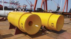
The LMUs – which consist of steel structures incorporating engineered elastomeric pads – make the transition possible by dampening the forces created, as the topsides' load is transferred to the tower.
The elastomeric pads are designed to take up the static and dynamic forces of the topsides structure, as well as the horizontal forces of open sea motions during the float-over mating operation. The vertical elastomer pads are normally complemented with horizontal elastomeric pads. Using data provided by the offshore consultants on the expected loads and movements, the elastomeric pads are engineered and calculated with non-linear finite element analysis (FEA), to achieve the expected spring stiffness for this crucial task.
The assembled LMU can be installed on either the topsides or jacket. For the Buoyant Tower project, LMUs were installed underneath the topsides with deck leg casing. The LMU receptor heads and stabbing cones, welded to the tower, were the contact points between the topsides and the tower.
DSUs are also important components for safe float-over operations. The topsides is loaded onto the vessel with a deck support frame and the DSUs are then placed between them to absorb the weight of the topsides. This enables the LMUs and DSUs to work together in synchronization. When the heavy vessel starts to ballast, decompression will occur on the DSUs and vertical compression will occur on LMUs.
The fendering systems are commonly used to absorb the impact of the heavy vessel and the tower as it moves forward or sideways during the mating operations. After the installation is completed, the topsides structure is welded to the tower. This concept can also be applied to spar, semisubmersible, or TLP designs.
FEA design calculations are carried out to identity the high stress build-up area and potential of buckling due to the unstable elastomeric column. Full-size tests help to validate the performance characteristic of the LMU design during the mating process.
Stringent quality control and testing requirements
Weather and sea state conditions are often affected by location, which naturally impacts vessels in many ways, making it imperative to thoroughly test the specific combination of weather and vessel for each application.
With the ability to perform full-size LMU compression testing to maximum design factored load capacity, it is recommended to specify units that are tested using a press with a capability of 18,300 metric tons (20,172 tons) for the most accurate results. All LMU elastomeric pads shall be tested to verify their non-linear stiffness behavior, before the site installation occurs.
Designed to perform
With a large amount of load placed on the elastomer pads during the float-over process, it is key that a high performance product is specified. Without second chances, every effort must be made to achieve perfection. To ensure this, an understanding of the characteristics and benefits of the elastomeric materials used in the float-over process are important. For example, the number of elastomeric layers and its size will influence the vertical non-linear stiffness.
Conclusion
Innovations within the offshore oil and gas industry have developed rapidly in recent years. As the unpredictable environment continues to produce new challenges, concepts such as the new Buoyant Tower will emerge. Due to the high stakes involved in offshore oil platform construction, specifically during the complex float-over process, it is imperative that only the most advanced products and solutions are used.


