Subsea compression: A future option for efficient oil and gas field developments
Bernt Bjerkreim - Norsk Hydro ASA
The main Ormen Lange gas field reservoir drive is pressure depletion. Estimated recoverable reserves are based on the future compression facilities for pressure boosting upstream from the onshore plant as reservoir pressure declines.
The Ormen Lange gas field is 100 km (62 mi) off the northwest coast of Norway on the Norwegian continental shelf in water depth varying between 850 and 1,100 m (2,779 - 3,609 ft). The reservoir is 40 km (25 mi) long, 8 to 10 km (5 - 6 mi) wide and 3,000 m (9,842 ft) below the surface. Recoverable reserves are estimated at 397 bcm (14 tcf) of natural gas and 28.5 MMcm (1 tcf) of condensate. Full production is scheduled for the fourth quarter of this year.
Ormen Lange’s subsea units and layout are designed to be flexible enough to determine the type of offshore compression at a later stage. The options are subsea compression and topside compression on a platform.
The final offshore compression concept decision can be postponed for a number of years after subsea production startup. An evaluation of the maturity of the technology and risk assessment for the two alternatives will be performed when required, as determined by production. This, in combination with pressure boosting onshore, upstream of the processing plant, will define the best timing of further compression facilities offshore. Commercial startup of offshore compression in 2014 is the earliest need date for offshore compression.
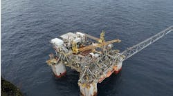
Topside compression, represented by a semisubmersible, is chosen as the base case for offshore compression.
Subsea control of the gas production, MEG supply, etc., would remain at the onshore terminal, even if an offshore compression platform is installed.
Installation and commissioning related to the offshore compression will have minimum impact on continued gas production from the subsea production units
Export temperature: 50ºC (122ºF
Design premise
The facility design basis describes the purpose of the future compression facility. Early production includes production prior to installation of future compression facilities, installation of future compression facilities, and a flowing wellhead pressure of 140 bara (14 MPa) which is required to meet an onshore arrival pressure of 75 bara (7.5 MPa) and a sales gas export rate of ~2 MMcf/d. This will determine timing on installation of the future compression.
Offshore compression
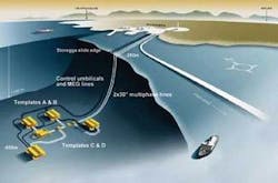
The offshore compression will be designed to receive the wellstream from each of the four template headers on the two initial templates (A and B) and to receive the wellstream from the two future templates (C and D). It also will need to distribute the compressed wellstream to each of the two 30-in. (762-mm) pipelines, and possibility to distribute the compressed wellstream to the optional third 30-in. pipeline.
The offshore compression platform will include two compressor trains and local (offshore) power generation.
A flowing wellhead pressure of typically 100 bar (10 MPa) corresponds to a platform top riser pressure of typically 90 bar (9 MPa) at the target sales gas export rate. A minimum flowing wellhead pressure during tail production of typically 60 bar (6 MPa) corresponds to a minimum platform top riser pressure of typically 50 bar (5 MPa).
The subsea gas compression station(s) will include power distribution equipment designed to receive the required amount of power from the main transformer, distribute the electrical power to all users, and individually regulate the speed of all electrical motors.
The required power will be delivered at Ormen Lange via a main power cable. The power system will be designed to deliver the required electrical power and transform down the power from the transmission voltage and down to a distribution voltage level, supply all control functions, enable power connection to the power distribution equipment, and enable control connection to the gas compressor station(s).
The future compression platform will be required when the wellhead pressure decreases so that the desired flow rate to the onshore facilities cannot be maintained without boosting. The topside design is based on minimum processing of the fluid. Processing will involve separating the gas and liquid phases, compressing the gas, and boosting the liquid. The gas and liquids will be mixed and transported to shore in the same multiphase pipelines used prior to platform installation for further processing onshore.
The capability to bypass the compression platform will be designed in.
For the minimum processing platform, the focus has been to keep the process as simple as possible. A two-train configuration has been chosen to limit equipment size. The challenge with this configuration is to have high energy efficiency throughout the lifetime of the installation. Rebundling of the compressors is planned.
The current driver chosen for each of the compressors is an LM2500+ turbine. The LM2500+ capacity is big for the initial phase and small for the later phase. Future investigations will consider a compressor selection that by means of later rebundling, could make up two 100% units in the initial phase and two 50% units in the later phase, with the higher pressure ratio. BAT evaluations will be performed in basic design with regard to overall energy efficiency.
The 24-hour-a-day control and monitoring of the platform will be done from the onshore CCR. The platform CCR will normally be manned during daytime by an operator, while there are field operators on the platform continuously accessible by wireless communication.
The main power supply configuration is 2 x 100%, two gas turbine driven generators with LM1600 gas turbines. Emergency power is supplied by 2 x 100% diesel driven generators.
The semisubmersible is a four-column structure with a quadrangular pontoon supporting the deck structure. The term “lower hull” identifies the hull up to the top of the columns, while “upper hull” means the deck structure from the top of the columns and including the main deck.
The pontoon is flexible regarding riser connection/hang-off. It also has advantageous strength characteristics for temporary conditions (transport/mating). The cross sections of the pontoons are rectangular to ease fabrication and to improve motion characteristics through high natural damping. The pontoon height is based on experience from similar constructions mostly related to strength required to ensure robustness with respect to the longitudinal center of gravity. The pontoons are asymmetrical.
The length between columns is both NS and EW c/c 66.56 m (218 ft). The column dimension is 17.92 x 17.92 m (59 x 59 ft) with a bilge radius of 5.76 m (19 ft).
The main load-carrying element of the upper hull is a rectangular box structure with the perimeter aligned with the outer edges/center bulkheads of the columns in transverse and longitudinal direction. The living quarters is a separate module supported at the main deck level.
The prevailing wind is from southwest. The living quarters are at the west side of the deck, with the helideck above in the southwest corner. The flare is in the northeast corner opposite the helideck.
The overall dimensions of the deck are as follows: 93.5 m (307 ft) long x 66.56 m (218 ft) wide. That includes the living quarters and riser balcony. The total area for the process is approximately 2,900 sq m (31,215 sq ft) on both main- and cellar-deck levels. This includes area taken up by walkways plus future and spare areas. The upper process deck (main deck) is 8 m (26 ft) above the cellar deck.
The CCR and CER are on the mezzanine level underneath the living quarters. A workshop and central stores are close to the living quarters on the main deck. Direct walkways and escape routes lead to the lifeboats from the workshops. Forklift access is provided to the workshop and central stores. A fire/blast wall segregates the process area from the utility area. A main transport and walkway is located on both deck elevations.
For vertical transport, an elevator is situated near the workshop and main stores. One pedestal crane is on the south side. The pedestal crane is for common laydown and laydown for the living quarters. The crane also can be used to assist in installing future equipment in spare areas. There is an elevator in both the northwest and southeast shafts for vertical transport of goods down to the hull,.
Both emergency generators and firewater-pump generators are on the cellar deck.
Due to equipment limitations (vessel sizes and compressor drivers), the main process is divided into two parallel trains. Each train has a supply header connected to dedicated risers. The supply headers for the two trains are not connected.
A subsea manifold system makes it possible to route the different wells to both supply headers, depending on the characteristics of the wells. The two pipelines to shore can be operated at different pressures. The process system is designed for full shut-in pressure. High integrity pressure protection solutions are feasible and will be considered in the basic concept engineering.
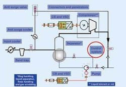
Each gas train consists of a two-phase inlet separator, two parallel suction coolers, a suction scrubber, a gas compressor, and two parallel after coolers. Each liquid train consists of a condensate booster pump and a condensate export pump. The two trains share spare pumps.
Subsea compression
Subsea compression is estimated to have a significantly lower investment cost than the platform compression alternative, with the same core functionality of compressing gas for transportation purposes to shore for further processing and export.
A subsea compression system is not qualified. If such a system were to be qualified at the time of concept selection for offshore compression, the advantages would include lower investment cost and reduced operational cost.
To ensure qualified equipment, two years of pilot testing has been proposed for the subsea compression system. Qualifying subsea compression also might yield a more cost-effective design for the offshore platform alternative.
Subsea compression piloting is scheduled to be in a dedicated test pit at Nyhamna. After testing, the pilot equipment might be used as an additional export compressor at Nyhamna or be included offshore in a satellite development tied back to existing infrastructure.
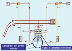
To compare platform compression to subsea compression, the subsea compression alternative has to have the same functionality as the platform alternative. The subsea compression alternative will be arranged so compression power can be used for the two first templates and two pipelines. It also will need the capability to compress gas from all four potential templates and to deliver the compressed gas to both pipelines to shore and to a third potential pipeline.
The physical interfaces between the initial Ormen Lange development and the subsea compression alternative will be the same as for the platform compression alternative.
The subsea compression station will be adjacent to the well templates. The discharge from the compression station will be connected directly to the two multiphase pipelines transporting the gas to the land-based gas processing facilities via four 16-in. (406-mm) spools.
Subsea compression consists of the subsea compression station and the long step-out power supply. Designs have been drafted with selected vendors in order to identify critical components for each of the two parts. All results will be supplied to potential main contractors. At the completion of this maturity phase, all prequalified main contractors will engage in competitive tendering for the subsea compression pilot.
At completion of the subsea compression pilot and the subsequent two-year testing period, the subsea compression system is regarded as fully qualified.
A generic pilot set-up has been developed to ensure competitive tendering and to include all components which might be required for a future subsea compression system. All main contractors competing for the subsea gas compression system pilot must adhere to this generic pilot setup.
The generic setup offers flexibility with regard to future technical content and to market competitiveness. This puts the focus on a compression system rather than compressor technology, while requiring vendors to demonstrate if some functionality can be omitted. Final optimization of the compressor system may be postponed until after qualification rather than as a prerequisite for the technical qualification and piloting activities.

