This article introduces ship motion and describes typical setbacks caused by motion. Facilities engineers must recognize and compensate for these effects when designing a separator for installation on a floating facility.
Freedom of motion
A free-floating ship has six degrees of freedom of motion: three rotations (angular movements) and three displacements (linear movements). The rotations are pitch, roll, and yaw. The displacements are surge, sway, and heave.Imagine an x-y-z coordinate system with its origin at the ship's center of gravity. The x axis is along the long axis of the ship. The y axis is along the transverse axis. The z axis is vertical. The terms roll, pitch, and yaw represent rotations about the x, y, and axes, respectively. Surge, sway, and heave represent displacement along the x, y, and z axes, respectively.
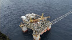
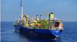
If the ship is moored, some of these degrees of freedom can be either eliminated or neglected. Floating production, storage, and offloading vessels, for example, generally weathervane on a turret located at the bow.
This mooring arrangement virtually eliminates surge, sway, and yaw, leaving only pitch and roll with some heave. Fixed structures such as tension leg platforms (TLPs) will demonstrate only the horizontal displacements: surge and sway.
Separator's resultant motion
The ship's movements are just the beginning. The resultant motion imparted on the process equipment must be determined so that the motion's effects on the performance of the equipment can be predicted. The goal is to design the equipment so that it will perform satisfactorily while operating under these conditions.The separator's resultant motion depends not only on the ship's motion, but also on the position of the equipment relative to the ship's center of gravity. No matter where the separator is located, its rotations are equal to the ship's by the theory of superposition.
Displacements, however, are not so simple. For equipment not located at the ship's center of gravity, the resultant displacements can be significantly greater than the ship's displacement. For example, heave at the ship's bow is amplified proportionally to the ship's pitch and the distance from the ship's center of gravity to the bow.
As a result, separators that are more sensitive to motion should be located near the ship's center of gravity. Separators that are less sensitive to movement can be located farther from the ship's center of gravity.
Effects on performance
A typical phase separator is a settling tank where the phases to be separated are allowed to still for a given period. During this time, gravity pulls the heaviest phase to the bottom and lets the lightest phase float to the top. A calm, motionless environment promotes gravity-driven separation. Imparting a motion to the separator causes the liquids inside it to slosh. Motion and sloshing can generate four modes of disturbance: spirit level, resonant waves, primary liquid turbulence, and secondary liquid turbulence.The fundamental mode of disturbance is the spirit level. When a separator tilts from the horizontal, the liquid level, which must remain coplanar to the earth's surface, is now tilted relative to the separator. This new apparent level is called the spirit level.
When the separator is pitched back and forth, the rising and falling action causes the cross-sectional area above the liquid level to decrease and increase as the level goes up and down.
This change in cross-sectional area changes the gas velocity and directly affects the separator's gas capacity. Gas velocity increases at the location of high waves, thus decreasing the size of liquid droplet that will fall out while increasing the risk of liquid re-entrainment. For proper gas/liquid separation, the vessel diameter should be selected to meet gas capacity requirements at the highest pitch.
The rising and falling level described above will develop into a wave motion as the frequency of the pitching motion increases. Resonant waves form when the cyclic pitching occurs at a frequency near the natural frequency of the liquid in the separator. These resonant waves can severely reduce the effectiveness of oil/water separation - especially for separators that rely on internal components such as buckets or weirs.
Waves impinging on the oil bucket of a three-phase separator can promote water carryover into the bucket. To maintain proper performance, the oil pad thickness should be increased.
As slushing and resonant waves become more significant, the waves' velocity can become high enough that turbulence forms in one or both of the liquid phases. This type of turbulence is called primary turbulence. Given enough wave energy and turbulence, the interface tension at the oil/water interface can be broken, and phase mixing can result.
Secondary liquid turbulence is similar to primary turbulence, except that secondary turbulence is generated by the liquids passing through the vessel's internals. These internals may he typical components such as structured packing. They also may be items that are installed in sloshing vessels specifically to reduce wave action.
Wave baffles or packing that are installed to reduce wave action and primary turbulence can actually degrade performance. Droplets jetting through the perforations can be sheared into smaller droplets, which can degrade the separator's performance. Similar to primary turbulence, secondary turbulence at interfaces can also result in phase mixing. Before internal components are installed to reduce problems associated with separator motion, the potential for detrimental effects should be considered.
Effects on level control
No matter which modes of disturbance are present in a process separator or how the separation process is impeded, simply measuring and controlling interfaces or levels becomes difficult. Sloshing due to pitch can cause a cyclic high-and-low wave action that makes level control difficult.To minimize these effects on level instruments, these devices should be placed on the axis of least pitch. The level at this location more closely represents an average level, instead of the extreme alternating highs and lows experienced at the ends of the vessel.
Vertical acceleration associated with heave causes displacers in level transmitters and controllers to give erroneous readings. To ensure proper level and interface control, an adequate vertical margin should be added to the diameter of horizontal separators and to the height of vertical separators.
Level switches should be located such that those with control functions operate as needed and those with safety functions do not cause nuisance shutdowns.
Vertical towers
Motion can degrade the performance of vertical towers such as glycol contactors, absorbers, and strippers. Although these vessels are mass separators, not phase separators, they still rely on gravity to perform properly, and their gas/liquid interfaces are sensitive to motion.The performance of towers can be significantly degraded when the tower is subjected to tilt. The spirit level effect can cause liquids to overflow the tray and gas to bypass the liquids. As a vertical column is tilted, the effective cross-sectional area of the vessel decreases. Liquid distribution from downcomers will obviously fall directly downward and will not be parallel to the wall of a tilted column.
To prevent performance degradation due to tilt, vessel diameters may have to be increased. Tray or packing designs should be carefully reviewed. Additional redistributors should be added to collect the liquids that have accumulated on the vessel wall and transfer them back into the gas flow. The manufacturer of the vessel internals should be informed of the motion so that modifications to the design can be made.
Over the past few years, several manufacturers and research institutions have published research papers and articles on the effects of motion on process equipment. The research goals have been to develop methods of modeling internal wave action and to predict its effects on performance.
Manufacturers, of course, have tried to develop devices or designs that reduce performance degradation due to motion.
Author
Wayne Mueller is a facilities engineer with Paragon Engineering Services in Houston. He has a BS in mechanical engineering and a MS in petroleum engineering. For further information on this subject, send an e-mail message to [email protected].Copyright 1997 Oil & Gas Journal. All Rights Reserved.


