MOORING/ANCHORING TECHNOLOGY: 250-ft tall turret with 45 risers, 10 mooring lines squeezed into Espadarte FPSO
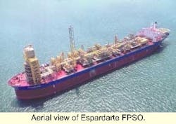
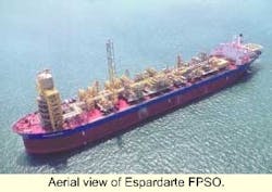
From its origin in 1975 as a large crude oil tanker through two metamorphoses, the 1,138 ft-long Espadarte floating produc-tion, storage, and offloading (FPSO) vessel has always represented size. The vessel first went into oil field service as the SBM-owned 275,000 dwt FPSO VI, equipped with a soft yoke mooring to a tower at its stern.
The vessel has evolved into its present form as the internal turret-equipped Espadarte FPSO. During part of its life as the FPSO VI, which operated for 12 years in the Ashland field offshore Nigeria, it was the largest such vessel operating. But size doesn't necessarily translate to space inside such a vessel.
For its current assignment in 2,640-ft water depths in the prolific hydrocarbon-producing Campos Basin offshore Brazil, the vessel received a new 100 ft-high by 56 ft-diameter internal turret, plus above deck structures totaling 250 ft in elevation, supplied by SBM-Imodco (Houston).
SBM-Imodco, one of the companies in the IHC Caland Group, owns and operates the Espadarte FPSO on a lease arrangement with Petrobras. The other two IHC Calland Companies involved in the design of this project were SBM of Switzerland and Gusto Engineering of Holland. The FPSO is operated by a fourth company in the IHC Group, SBM Production Contractors. This FPSO represents the eleventh floating system leased and operated by the IHC Group.
The topsides were fabricated as a number of modules, each weighing between 100 tons and 500 tons. The modules were interconnected to form the complete oil, gas, and water processing facilities. The conversion project also included reconfiguring the interior of the vessel's hull to accommodate the storage of 1.9 million bbl of crude oil.
Other modifications included provision for offloading via shuttle tanker, accommodation, and utility services. The resulting large complex unit has all the features necessary for enhanced oil recovery using water and gas lift. It also can remain on station for up to 13 years without dry-docking.
Turret mooring design
The FPSO's turret was sized to accommodate 45 risers ranging from 4 in. to 8 in. in diameter in the moonpool. This configuration would allow production of up to 100,000 b/d of oil.
The turret features the world's largest non-segmented bearing measuring 25.6 ft in diameter. The bearing system allows the central fixed part of the turret to be permanently anchored to the seafloor, while the hull is allowed to freely weathervane around the turret in response to the forces of wind, wave, and current.
To haul in the risers, the turret is equipped with a 250-ton main winch and a 50-ton auxiliary winch, provided by Appleton Marine. Appleton also provided the 400 hp electro-hydraulic power unit for the winches and chain jacks. The two winches and power unit are installed on the winch deck of the upper turret superstructure. Thus, the vessel can weathervane without restriction during tensioning of the risers and mooring lines.
The mooring system consists of a 10-point chain/polyester, rope/chain system. A bottom length of chain is connected to the SBM Mag anchors. The mid-section is polyester, and the top section is chain. The chain is studless 4 1/2-in. ORQ Grade 3 with a rated breaking strength of 982 Tonnes. Chains are routed into the turret through curved hawse pipes.
The hawse pipes are located around the circumference of the turret, between risers, in two groups of three and one group of four. A crossarm with integral chain stopper is permanently attached to the top of each hawse pipe. The turret structure includes a horizontal pipe located 16 ft above each chain stopper. The pipe serves as a turning shoe allowing the chain to pass vertically upward through the hawse pipe and stopper, over the turning pipe and back down into the moonpool.
Tight fit
As originally conceived, one winch would have been used to install the risers and be used for hauling in and tensioning each of the mooring chains. Due to the deep water and high mooring line loads, it became apparent that the diameter of the winch drum required was too large to realistically fit within the confines of the turret.
Additional complexities, due to the high loads, included very high level wind loads and the need for moveable sheaves, required for aligning the winch drum with the load. With these considerations, a simpler more compact solution was required.
Bardex Corp. (Goleta, Calif.) was asked to submit a design solution using its linear chain jack. With 45 risers and 10 mooring lines entering the turret, the application required a compact, high-capacity chain tensioning device, small and light enough to be lowered down into the moonpool, slipped between the risers, and onto each of the 10 chain stoppers.
Following chain tensioning, the chain jack would be removed. The chain deck would be submerged during long-term mooring periods. Due to potential stretch in the polyester rope, periodic re-tensioning of the mooring lines may require the re-installation of the chain jack.
Chain jack design
The design developed by Bardex was a compression style chain jack. The chain jack is composed of two hydraulic cylinders, a traveling crossarm with integral latches, cylinder connecting crossbeam with hydraulic manifold, and a separate cart-mounted control console. Traveling latches are opened and closed using an integrally attached hydraulic cylinder. The traveling cross-arm is bolted to the top end of each cylinder rod.
The traveling crossarm is slotted like a horseshoe in shape. This allows the entire chain jack to be installed or removed from a chain stopper without disturbing the chain. The chain jack is temporarily attached to the fixed crossarm/stopper using 12, high-strength M30 bolts.
Although one chain jack could be used at any of the 10 chain stoppers, three chain jacks (and three consoles) were ordered - one per group of chain stoppers, so that chain haul-in could be performed simultaneously at more than one chain station. To simplify movement of the chain jack, the turret was fitted with a circular monorail and trolley mounted 5-ton hoist for moving the 9,500 lb. chain jack from one stopper to the next.
The hydraulic manifold mounted on the cylinder crossbeam contains the relief, control, and overcenter valves for the unit. Jumper hoses with quick-disconnect (QD) fittings were used to connect the manifold to the turret ring main hydraulic supply and return permanent piping. Short length jumper hoses and QDs were also used for connecting the portable control console to the hydraulic manifold.
Operator control of the chain jack is the hydraulic control console, which includes main cylinder lift/lower control, traveling latch open control, and fixed stopper open control. A control console pressure gauge provides indication of load in tons and pressure in bar/psi. The tension in each mooring line is measured by instrumented links; tensions are confirmed by angle measurements.
Chain jack lift capacity was specified to be 325 tons at the specified speed, with a stall capacity of 400 tons and capacity fully retracted (structural) of 456 tons. With a 39-in. stroke, the extended height of the chain jack is 12.5 ft. Retracted height is 8.2 ft. The envelope area of the chain jack in the horizontal plane is 62 ins. by 32-ins. Specified haul in speed is 5 ft/min.
In addition to the benefit of compactness, the linear design of the chain jack provides a reduction in interlink chain stress and wear, when compared to a chain winch or wildcat. In the linear chain jack, links are loaded in tension only, exactly as the chain's fabricator tests the chain. The straight pull design of the unit thus avoids the added bending stress and inter-link wear inherent with chain winches in which individual chain links are hinged under tension.
Mooring operations
Witnessing the use of chain jacks illustrated the viability of this approach. The operation began with the Espadarte ballasted up at the bow. This attitude raised the chain deck in the turret 1-2 meters above the water, creating a dry, safe work place. Six messenger chains had been pre-installed. The inboard end was seated in the chain stopper. From the stopper, the chain trailed down through the hawse pipe.
The outboard end was lifted back up to the ship's foredeck where it was secured. The remaining sections of the mooring line had been deployed earlier and were buoyed-off for retrieval. Each chain jack and control console cart was lowered from the winch deck to the chain deck and installed on one of the 10 chain stoppers in each of the three groups.
The first anchor handling vessel (AHV) retrieved the first anchor line. Its related messenger chain was released from the bow of the Espadarte and passed over to a second AHV. The second AHV carried the end of the messenger chain to the first AHV where the messenger chain was passed across. On the first AHV, the messenger and mooring chains were connected and released overboard.
The messenger chain was then hauled in using the chain jack. It required approximately an hour to haul in the 300-ft messenger chain. Messenger chains were disconnected and the messenger chain pulled across the moonpool for use with one of the other mooring lines. The time required to shut down a jack, move it, and prepare it for hauling the next chain ranged from 1 to 2 hours.
On several occasions, it was decided to wait for two symmetrically opposed chains to be prepared. These were then hauled in simultaneously with the advantage of minimizing movement of the ship. In all instances, the chain jacks were repositioned and ready to haul chain well before the anchor handling vessels had completed the chain hookup.
Each of the 10 chains was connected and hauled in to pretension level. At this point, the mooring spread (AHVs and positioning tugs) was released. The FPSO was securely moored. Following the successful pre-tensioning, each chain was further tensioned to the final prescribed tension level. Chain jacks and consoles were then disconnected and lifted out of the moonpool and secured out of the way for long-term storage.
Conclusion
The mooring system design approach of using chain jacks in lieu of winches for deepwater/high load applications where there is minimum available space or where installation loads and wires would be too large was verified by the successful installation in the Espadarte FPSO.
There is a continuing need in the industry for turret moored vessels to perform floating prod-uction. Since the turret costs and vessel reinforcement increase exponentially with diameter, it is essential that riser and mooring lines be closely spaced.
As the water depths increase, the mooring line tensions will become greater. There will be a growing need to provide larger capacity mooring equipment that will fit in the confined spaces of the turret. The linear chain jack will be the equipment of choice for high-tension capacities in the most compact and lightweight package.
