Carmen Vieitez •Martin Cox
Baker Hughes
For an exploration and production company operating offshore Africa, the decision to use the Baker Hughes SeismicTrak seismic-while-drilling (SWD) service for a walkaway vertical seismic profile (VSP) operation enabled successful salt boundary identification in an exploration well while reducing rig time and risk, compared to a conventional wireline operation. The 1,500-shot survey line that was run is believed to be the first operation of its type conducted in a logging-while-drilling (LWD) environment. The survey fulfilled all data requirements, enabled the operator’s subsurface model to be updated, and successfully identified the salt boundary for optimal future well placements for hydrocarbon production.
Salt drilling and imaging challenges
During salt dome evolution, salt is uplifted, penetrating and deforming existing rock, breaking its continuity and thrusting it upward. The salt acts as an impermeable barrier for hydrocarbon migration, making the contact point between the surrounding sedimentary rock and the salt dome an excellent oil and gas reservoir. To maximize production, the goal is to place development wellbores as close to the upper boundary of the source rock and salt barrier as possible. The challenge comes in trying to identify the exact contact point between the salt dome and the reservoir, because drilling into the salt raises the risk of losing hydrocarbons into it.
When performing surface seismic, the variety of salt dome shapes makes it difficult to properly evaluate the travel time of acoustic waves through the salt. This makes it impossible to guarantee the accuracy of a subsurface model when using surface seismic to evaluate a salt dome. Borehole seismic surveys are the critical tie between surface seismic and petrophysical data. They provide high-resolution imaging of reservoir features around and beyond the wellbore for enhanced reservoir delineation, characterization, and monitoring.
Conventional wireline-conveyed tools and systems can interfere with drilling and consume rig time. Additionally, the geometry of horizontal wells makes it difficult to place a wireline geophone in the well, and the fact that proper wireline-conveyed seismic imaging of salt requires multiple downhole geophone positions exacerbates the situation.
Seismic-while-drilling advantages
SWD is deployed as part of the drillstring. It removes the wireline cable connection from downhole to surface, transmitting data to surface via mud-pulse telemetry or wired pipe, and synchronizes downhole and surface signals using highly accurate clocks. These capabilities save rig time, make it practical and efficient to perform horizontal surveys, and enable well teams to react to data and make informed decisions while drilling.
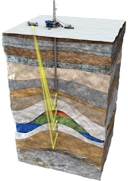
SWD incorporates the downhole tool into the bottomhole assembly (BHA) to deliver traditional borehole seismic measurements, (including real-time checkshot, interval and velocity data from multiple recording components such as X, Y, and Z geophone elements), plus a downhole hydrophone. A direct measurement of seismic travel times from a surface source to survey locations along the wellbore is provided. The times are used to place the bit on the seismic volume in time to track the well position while the section is drilled. Real-time waveforms can be sent to surface through measurement-while-drilling telemetry for quality control (QC) of downhole data. The data can be used to update the local surface seismic image, mitigating the depth uncertainty of surface seismic in real time. Capturing measurements during natural pauses in drilling minimizes the impact on operations and saves rig time. Real-time waveforms also enable potential forecasting hundreds, or even thousands, of feet in front of the bit, making it possible to take immediate actions to mitigate impending hazards and avoid target misses that can lead to unnecessary side tracks. The ability to reduce drilling uncertainty leads to better wellbore placement and decision making, which in turn can improve production, ultimate recovery and safety while reducing cost and non-productive time (NPT).
SWD can be especially useful when drilling through salt, which normally appears as blank spots on seismic maps. Using SWD, the bit can be placed on the seismic map while drilling, predicting target depths and identifying salt proximity and salt exits to adjust well trajectory to land the well in the best place in the reservoir and/or to update coring and casing points while drilling. The service provides input data to update pore pressure models while drilling, and to optimize mud weight for salt entrance or exit. Acquiring seismic data while drilling through the blind spot provide more details and delineates boundaries that are not discernible on conventional surface seismic. Being able to spot a hazardous zone or approaching bed can mitigate drilling risk to improve safety and further reduce cost.
How the SWD service works
The SeismicTrak downhole tool consists of a processor, memory, acoustic sensors, and a rugged, ultrahigh-precision clock that can maintain time accurately to less than one millisecond (ms) per 10 days. This accuracy is essential because the tool has no direct physical access to times from the global positioning system while it is downhole in the BHA. The tool is synchronized prior to running in hole and once again when it returns to the surface, to measure the time drift while downhole and ensure the quality of the measurements.
The surface seismic source is the same used for a wireline VSP survey: a high-pressure air gun array deployed a few meters below the water surface and controlled by a digital auto-tuning gun controller. For vertical or near-vertical wells, seismic sources are deployed from the rig. For deviated wells, seismic sources are deployed from a vessel located vertically above the acoustic sensor in the tool.
The tool has four component sensors: two sets of three geophones oriented orthogonally in x, y, and z direction, plus two hydrophone pressure sensors. For the real-time data where only one component can currently be transmitted to surface, the downhole hydrophone is used as the primary sensor, as it is omnidirectional and does not rely on coupling to the formation.
The downhole hydrophone is used as the primary sensor in a vertical well for the same reason.
Seismic data are acquired during drilling pauses (such as drillpipe connections) in an acoustically quiet environment, with no mud circulation or BHA movement. One of the key advantages of the service is that generally it does not interfere with the drilling process and avoids additional rig time. Typically 10 shots are fired with a shooting time interval of 10 to 15 seconds. After acquisition, the seismic trace is processed downhole and stored, and hydrophone data around the first seismic arrival are transmitted uphole by mud pulse telemetry. Once at surface, the break time of the first arrival on the waveform is picked and processed. The time-depth data is then used to position the well on the seismic section. The real-time data trace can be wavelet processed using normal VSP techniques to produce a reflection image. The full waveform is stored in memory for post-run processing and deliverables.
Case study
The operator of a well offshore Africa, who had used wireline-conveyed systems to perform previous walkaway VSP operations, chose SWD as the solution to reduce rig time and risk in a walkaway operation to update the existing surface seismic model, including a salt dome delineation, for optimum wellbore placement of future development wells.
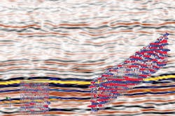
VSP data can be used to improve the salt boundary detection in an earth model by tomographically updating its position using travel times measured through the salt body and sedimentary layers. Additionally, the salt boundary can be estimated using the direct salt arrival time in the data, with the coordinates of source and receiver, the top salt (salt-flood model) and any sedimentary layer models. The two models are used to generate travel times, which are summed at every subsurface point and matched to the real data. The survey line for this survey was designed such that there would be areas of strong salt arrivals plus areas of strong sedimentary arrivals with transition areas containing both arrivals. The data then contained two main arrivals, referred to as direct arrivals - one through the sediment and one through the salt. When the source was near or over the salt, the high velocity of the salt caused the direct salt arrival to appear sooner than the sediment arrival, although sometimes both could be identified, which was useful in model updating.
The complex walkaway operation consisted of using a single, stationary, downhole receiver placed below the salt overhang, with the surface source moving progressively at a range of increasing horizontal distance from the wellbore. The complexity of the operation required extensive pre-job planning involving subject matter experts from the operator and the service company, clear identification of communication protocols and responsibilities throughout the operation, and 24/7 support by the service company wireline and borehole seismic experts on location and by remote connection to perform the operation and ensure proper real-time data quality control.
The operation was performed following a strict planned SWD shooting sequence while the boat traversed the shooting pattern, with continuous shooting at 20-second intervals, with occasional pauses for real-time data transmission to surface for QC, for 1,500 shots from surface positions to one downhole position.
The decision was made to obtain the data from memory only to minimize operational time, but occasional real-time data were sent to surface to confirm data quality and tool function. In these instances, pumps were briefly started to transmit the current downhole stacked trace to surface, and shooting continued after quality was confirmed.
Results
All data requirements for the project were fulfilled through 100% acquisition of the walkaway shoot points. Travel time input was delivered to the operator for a tomographic inversion of subservice model using sediments and salt arrival picks. As a result, the salt boundary was successfully identified to optimize future well placements for maximum hydrocarbon production.
The operation was effectively carried out according to plan, with no NPT. The amount of rig time saved by using SWD versus wireline was estimated at 24 to 34 hours.
