Two-million lb slip-based landing string extends drilling limits
James N. Brock, R. Brett Chandler, Michael J. Jellison - Grant Prideco LP
Leianne W. Sanclemente, Richard J. Robichaux - Workstrings LLC
Muhammad Saleh - Chevron Corp.
David Zaunbrecher - HTK Consultants Inc.
The challenge of setting of larger diameter and heavier casing strings with total setting hook loads approaching 2 million lb has been met by implementing a systems approach. The landing string system (LSS) provides engineered and matched equipment components required to successfully run long heavy casing strings including 1,000-ton (907-metric ton) elevators, 1,000-ton slips, and a 2-million lb landing string tubular assembly. This system offers the following advantages:
- The LSS adapts to differing rig conditions and maintains normal rig-up and pipe running procedures
- Range 2 pipe lengths and standard API RSC permit the use of available mechanized pipe handling systems and iron roughnecks
- Operational savings come from faster makeup and use of standard rig equipment
- The LSS limits the number of personnel required on the rig floor and use of familiar operating procedures promotes safe operations
- The LSS permits flexibility by using standard API RSC, conventional slip designs and elevators
- The LSS functions in all rig situations or unscheduled events
- The LSS can be matched with other conventional 6 5/8-in. (17-cm) landing strings to produce any configuration and to alleviate the need for pup joints, crossovers, or different handling equipment
- The LSS can be rotated and used to drill, if necessary. The LSS enables the drilling engineer to implement a casing program that provides a structurally sound well design, provides protection of the formation, and minimizes drilling time to reach the objective.
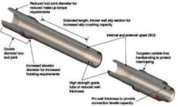
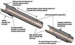
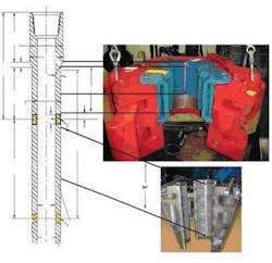
The 6 5/8-in., heavy wall, 150-ksi yield strength pipe incorporates an innovative thick-walled section in the slip contact area to resist slip crushing loads, and a uniquely designed dual-diameter tool joint to increase elevator capacity. Slips were engineered to equalize radial and axial loads, to increase the slip-to-pipe contact area, and to optimize the contact angle to minimize the crushing loads on the pipe body. Combined with 1,000-ton elevators, the system uses conventional rig-up and operating procedures.
Chevron at Jack
Chevron’s Jack discovery is in the US Gulf of Mexico approximately 270 mi (435 km) southwest of New Orleans and 175 mi (282 km) offshore in 7,000 ft (2,134 m) of water. The landing string system (LSS) was instrumental in the successful completion of this record well facilitating the landing of the 16-in. (41-cm) and 13 5/8-in. (35-cm) casing strings.
Matching the 6 5/8-in. landing string pipe diameter to the 6 5/8-in. drill pipe diameter used on the rig mitigated the need to change pipe handling and make-up equipment. In addition, both strings had 6 5/8 in. Full-Hole RSC. The rig crew was familiar with the equipment and standard rig processes. This enhances safe operations for the critical landing operations.
16-in. liner. Running the 16-in. liner was practice for the heavier 13 5/8-in. casing string. The 16-in. string was set approximately 1,600 ft (488 m) below the mudline and was comprised of 11,160 ft (3,402 m) of 16-in. 97 ppf set to a depth of 19,815 ft (6,040 m). The string was run in 11.8 ppg drilling fluid. The 16-in. liner and the 8,600 ft (2,621 m) of LSS had a total weight of 1,314,000 lb, excluding the 115,000-lb capacity block and top drive.
13 5/8-in. casing. The 13 5/8-in. casing string was the heaviest casing load designed. This intermediate casing string was a tapered string of 14-in. (35.5 cm) 114 ppf x 13 3/4-in. 100 ppf x 13 5/8-in. 88.2 ppf. It was set at 23,599 ft (7,193 m). The casing and landing string were run in 11.9 ppg drilling fluid and had a total weight of 1.65 million lb, excluding the 75,000 lb block. The 1.5-million lb capacity top drive was set back for this 13 5/8-in. casing run.
The casing was landed and spaced out to allow some of the casing string weight to land on the wellhead and some of the weight set on the slips to facilitate picking up the top drive. Once the top drive was picked up, the slips were pulled and the weight was distributed between the top drive and wellhead. This worked well and will be continued for future jobs.
The nature of deepwater and ultra deepwater well designs drives the requirement for higher tensile capacity landing strings. Target depths below the mudline also are extended. This, combined with the often narrow margin between pore pressure/mud weight and fracture gradient, causes well designers to set more intermediate casing strings. This, in turn, pushes large diameter, heavy casing strings to deeper setting depths to maintain hole size and to reach the intended hydrocarbon targets.
As operators and manufacturers investigated the requirements for ultra high capacity landing strings, slip crushing was identified as a major consideration. A basic problem is the tensile rating.
Slip-based landing string
To address slip-crushing, a slip-based landing string system was developed that uses pipe with a thick wall section welded between the upset and box tool joint. The pipe also incorporates a dual-diameter tool joint to increase elevator capacity. Specially engineered elevator and slip designs complete the ultra high tensile load capacity landing string system. This ultra high capacity system has been analyzed with finite element modeling and other analytical techniques, extensively tested and field proven. It has successfully landed heavy casing strings in deepwater with axial loads approaching 1.75 million lb.
To achieve a lifting capacity of 2 million lb, there are five design components to consider:
- Pipe body
- Heavy wall slip section (HWSS)
- Tool joint
- Rotary-shouldered connection (RSC)
- Weld.
Pipe body. A tensile rating of 2 million lb or more can be required. API Specification 5D does not include tubulars with the higher minimum yield strength and heavier wall thickness required for landing string applications.
The cross-sectional area increases more with increased pipe OD than with decreased pipe ID or increased wall thickness. This, plus the improved hydraulics for circulating and cementing with a larger ID, dictates that the largest pipe diameters possible are used. However, matching the landing string pipe diameter to the drill pipe diameter used on the rig, mitigates the need to change pipe handling and make-up equipment.
API standards for new drill pipe require that the minimum pipe body wall thickness be at least 87.5% of the nominal pipe body wall thickness. For landing string applications, it is recommended that the minimum pipe body wall thickness be increased to at least 90% of the nominal pipe body wall thickness.
There now are proven high-strength proprietary grades available with specified minimum yield strength (SMYS) of 140 ksi and 150 ksi. Use of these grades provides increased lifting capacity of approximately 11%. With current metallurgy, pipe with 150 SMYS can be produced with minimum toughness greater than standard API S-135 produced in the past.
Heavy-wall slip section. For increased tensile load applications such as landing operations, slip crushing of the pipe body is an important consideration. When slips are placed to support the string in the rotary, they exert a radial force on the pipe that creates a collapse force inducing a hoop stress that increases with increased axial load. Slip-crushing capacity depends on the pipe body OD, wall thickness, and SMYS. The heavy-wall slip section provides a thicker wall in the slip-contact area. In addition to a heavier wall, the machined OD and ID surfaces of the heavy-wall slip section provide improved concentricity and ovality to further increase slip-crushing resistance.
Slip-crushing capacity depends on the contact area of the slip-inserts and the transverse load factor for the slip unit. The transverse load factor depends on friction between the slips and bowl and the specific slip design.
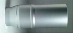
The heavy-wall slip section design can increase the slip-crushing capacity by providing a heavy-wall section in the slip-contact area. The design criteria of the heavy-wall section are based on formulas developed by S.H. Spiri and W. B. Reinhold. The heavy-wall slip section OD must equal the pipe body upset diameter, DTE, and the ID is sized to provide a slip-crushing capacity equal to or greater than the pipe body tensile capacity. In addition, the tensile capacity of the HWSS must be verified.
The slip-based landing string is designed with three welds, one at the tube to pin tool joint, one at the tube to heavy-wall slip section, and one connecting the heavy-wall slip section to the box tool joint. For welding, the HWSS material must be compatible with both the pipe body upset and the tool joint.
Tool joint. Due to manufacturing requirements, the ID of the tool joint must be equal to the ID of the HWSS. A balanced tool joint configuration maximizes the fatigue resistance and torsional balance of the RSC. The design criterion for a balanced configuration is the ratio of the area of the box divided by the area of the pin equals 1.00 to 1.15.
Tool joint OD is also critical in determining the elevator capacity of the landing string assembly. The elevator capacity is the product of the horizontal projected contact area of the 18° tool joint shoulder against the elevator bushing times the lesser compressive yield strength of the two contact surfaces. Typically, the elevator bushing has the lower yield strength of the two components, 110,100 psi versus 120,000 psi for the tool joint. Elevator capacity curves can be generated to determine the reduction in lift capacity from tool joint OD wear.
To meet the two differing tool joint OD criteria, balanced configuration, and elevator capacity, a dual-diameter tool joint can be used. For landing string applications, the dual-diameter tool joint provides one diameter to meet the balanced configuration requirement and to provide for fishing needs; and a larger second diameter to meet the elevator capacity requirement.
Rotary-shouldered connection. For drilling, API Recommended Practice 7G(4) defines the tool joint tensile rating as the cross-sectional area of the pin at the gauge point times the SMYS of the tool joint material. For API rotary-shouldered connections, the box is not considered in the tool joint tensile rating because the box critical area, the area of the box at the weakest point under a tensile load, is larger than the area of the pin at the gauge point. It is recommended that all connection tensile parameters be evaluated to determine the RSC’s tensile rating including pin critical area, box critical area, thread shear area, and thread bearing area. For the landing string assembly, design criteria for the connection tensile rating is defined as greater than or equal to the pipe body tensile strength for 100% RBW.
The final criterion to be considered for the RCS is the tensile load required to separate the external torque shoulder. The external torque shoulder serves as the pressure seal for the RSC. The sealing mechanism is generated by the compressive force between the external shoulder surfaces resulting from the makeup torque (MUT). Tensile loads tend to unload this compressive force and high tensile loads, as would be expected for a landing string application, can result in separation of the shoulders and loss of the sealing mechanism. A proper seal is required since the landing string must circulate drilling fluid during the landing operation and circulate cement.
Separation of the external torque shoulder is a function of the makeup torque, the tool joint configuration, the tool joint material yield strength, and the amount of externally applied tensile load. The design criterion for minimum shoulder separation tensile load, made up to minimum MUT, is defined as greater than or equal to the pipe body tensile strength for 100% RBW. A torque-tension chart gives the shoulder separation, connection (pin) yield, pipe body yield, makeup torque range, and landing string rating.
Slips
A slip system to handle this 2-million lb landing string must provide efficiency on the rig with standard pipe running and handling processes that would require the following objectives to be met:
- Base modifications on a conventional slip design
- Improve distribution of the transverse load to increase the slip-crushing capacity
- Achieve 2 million lb slip-crushing capacity on the landing string
- Develop a hydraulic actuated slip system
- Develop a slip system all rigs can use.
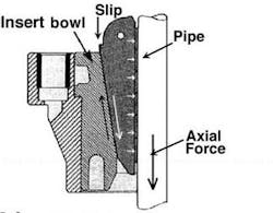
When slips are set around a tubular, the slips exert transverse loads to the drill pipe which convert to hoop stress in the tube. Excessive hoop stress creates the force that can damage the drill pipe. If the pipe begins to collapse, the slip looses contact and support with the insert bowl; the toe of the slip can break loosing contact with the pipe; the slip inserts can then fall possibly dropping the pipe.
Slip tests on drill pipe confirmed it was the highest stress concentration in the standard slip design is at the toe of the slips. This is the thinnest section of the slip segments. It is also the most vulnerable to increased stress due to wear in the insert bowl supporting the slips. The stresses on the toe of the slip greatly increase without support of the insert bowl.
The challenge for improving slip-crushing capacity to reach 2 million lb was to improve the distribution of the load across the length of the slip body and to reduce the transverse load effect by increasing the radial load into the rotary table and away from the drill pipe tube.
The two variables in the slip-crushing load equation, PSCC, related to the slips are the length of contact between the slip inserts and the pipe body; and the angle of the slip contacting the insert bowl. Increasing the length of the slip contact to the pipe body will increase the calculated slip crushing capacity 6 to 11%. The increase in length with allow for greater area for load distribution. By modifying the slip angle, the calculated slip-crushing capacity can be increased 3 to 8%. The modified slip angle improves the transverse load effect by shifting the radial load more to the solid insert bowl, and protects the toe of the slips while protecting the pipe.
This new slip design uses independently supported slip inserts with the groove/ledge design and adds a row of inserts from 16 in. to 20 in. of insert length. This allows for a full continuous 20 in. of slip-to-pipe contact length. An increased slip angle was tested and improved slip crushing capacity compared to the standard 9.46° slip angle. For optimum tolerances and optimum slip-crushing capacity, the insert bowl is solid. The internal angle of the solid bowl matches the slip body optimum angle to maintain dimensional integrity. To further improve the tolerances, a split master bushing accompanies the system to fit the rig’s rotary table.
Typically, slips are tested and rated using a solid bar to achieve the API design factor and to determine if the slips will be damaged. To test for slip crushing, an actual pipe sample is used with strain gauges to measure the stresses. This 20-in. slip design was tested to verify the improvement in slip-crushing load capacity using a hydraulic load frame capable of 2 million lb. Both external and internal strain gauges were placed on the 6.906-in. OD HWSS test mandrel to measure the stress in the pipe at various points.
The test verifying the design proved that a 2-million lb axial load could be achieved before measuring yield on the strain gauges of the new HWSS landing string
Elevators
The elevators to complement this 2-million lb LSS required modifications to the current available 750-ton (680-metric ton) hydraulic elevator systems. The following objective had to be met:
- Quick change of inner elevator bushings during casing running operations
- Qualify an elevator/inner bushing design for 1,000-ton hoisting capacity
Current hydraulic 750-ton elevators are rated for 750-ton hoisting capacity with an API 18° taper on drill pipe. These elevators can be used to run risers with a special square shoulder riser bushing, giving the elevator an increased hoisting capacity of 1,000 tons. The API 18° taper on the drill pipe box sits on the corresponding tapered load shoulder in the elevator bushing halfway up the vertical height. The square shoulder riser bushing has the load shoulder located at the top of the bushing.
Finite element analysis determined the box tool joint taper and the matching load shoulder taper of the elevator bushing required to obtain a 1,000-ton load rating. The FEA model using actual strain gauge data from the load test calculated that a 45° taper placed at the top of the bushing would improve the loading to meet the design qualifications. A design verification test was run on an elevator/bushing configuration with a 45° load shoulder taper placed at the top of the bushing. This configuration was load tested to 5.6 million lb to certify the design for 1,000 ton. At this position, the load can be distributed more evenly onto the body of the elevator. The landing string box tool joint taper was specified also at 45° to match the 1,000-ton elevator bushing.
Acknowledgements
The authors thank the management of Chevron Corp. Inc., Hess Corp. Inc., HTK Consultants Inc., Grant Prideco LP, and Workstrings LLC for their support and encouragement in publishing this paper.
