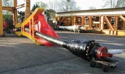
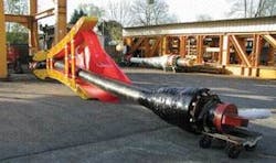
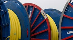
The arrival of high-pressure applications above API 10,000 psi represents a challenge for large diameter flexible pipes. The first API 15,000 psi (103 MPa) flexible line for kill and choke applications was produced in 1976 with a 2.5-in (63.5-mm) ID. The design has been improved since to the present 3-in. (76-mm), 15,000 psi, 100°C (212°F) Rilsan and 130°C (266°F) Coflon products.
Flexible pipe technology
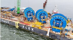
Unbonded flexible pipes commonly are used for dynamic risers connecting seabed flowlines to floating production facilities, as wellhead jumpers on floating dry tree units, for fluid transfer lines connecting two production facilities, and for static seabed flowlines and jumpers.
The tensile armor layers are high-strength carbon steel rectangular wires, wound in opposed directions to provide torque balance. These layers provide the mechanical resistance performances of the pipe; that is, resistance to hoop stress, tension, and hydrostatic pressure. The plastic layers are pressure barriers against internal and external fluids. Combined design pressure and temperature are critical for the selection of the polymer used as the leak-proof barrier (pressure sheath). Polymers commonly used are polyethylene, polyamide 11, and PVDF. PVDF has the best chemical compatibility and highest continuously sustainable temperature of 130°C (266°F). For high-pressure applications, an additional layer of helical reinforcement over the pressure armor, or a second set of tensile armor layers, can be applied. For deepwater designs, additional reinforcements are applied over the tensile armor layers to avoid buckling under the external compression load.
For applications requiring high thermal performance, insulation layers such as syntactic foam strips can be wound on the pipe.
Flexible pipes have excellent fatigue behavior for floating platforms. They follow wave-induced vessel motions and resist environmental loadings thanks to their ability to bend to small radii.
High-pressure fatigue
Fatigue is a driving parameter for dynamic-flexible risers design. The fatigue life of the tensile and pressure armor layers dictates the life of the flexible pipe. Therefore, an important step is predicting expected life of the primary structural layers using valid fatigue-life models.
When flexible pipe is bent, the layers and the wires in the each layer slide, adopting the new shape. When the pipe is not pressurized, there is little resistance to sliding. In this case, sliding of the wires occurs for very small curvature variations. However, when the pipe is pressurized, a contact pressure pushes the layers and the wires against each other. When a moment is applied, a friction force prevents the wires from moving until the moment is large enough to overcome the friction. The higher the operating pressure, the higher the forces in the wires before sliding, and thus the higher the stresses and the larger the fatigue damage. In high-pressure and ultra deepwater designs, the tensile armors as well as the pressure armors are challenged.
With new developments requiring HT/HP flexible pipes, the high temperature became an issue. A North Sea reservoir with the highest pressure and highest temperature on the Norwegian continental shelf so far at 910 bar (91 MPa) and 170°C (338°F) was a challenge for flexible risers.
At the flexible riser connection, the temperature is lower due to cooling in the flowlines resulting is a design specification of 132°C (270°F). These challenges for the 10-in. (254-mm) flexible production risers were increased by H2S and CO2 in the production fluid requiring sour service steel for the riser armor layers.
Qualification testing included not only small-scale tests, but also a full-scale fatigue test under combined tension, pressure, and temperature loads. Fluid temperatures up to 130°C (266°F) were applied, and the flexible pipe passed the test.
These flexible risers hold the design temperature record at 132°C (270°F) with the ability to withstand short periods with the internal fluid at 150°C (302°F).
To exceed 130°C (266°F), several studies were performed. The MERL/MCS JIP (Evaluation of Polymers for High Temperature Flexible Pipes) explored how to qualify a high-temperature resistant polymer. The conclusions were compiled into API 17TR1. It describes the processes by which the critical material properties, both static and dynamic, can be measured and evaluated against relevant performance criteria.
The HP/HT JIP with BP, ExxonMobil, and Technip pursued research and development in the HT area. Several options were studied to allow flexible pipes to carry HT fluid, i.e. more than 130°C (266°F). This JIP led to development of a thermal screen that enables flexible pipes to carry fluid with temperatures up to 150/170°C (302/388°F).
Two PVDF grades already qualified up to 130°C and API 15,000 psi operating conditions. Using an internal thermal screen, a bore temperature of over 150°C (302°F) can be sustained while not exceeding 130°C (266°F) at the pressure sheath level. The screen is laid onto the internal carcass and thermally insulates between the fluid in the bore and the polymer pressure sheath. This is a Technip patented technology.
HP, ultra deepwater
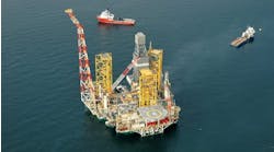
Flexible pipe was chosen for the water injection system at a BP deepwater Gulf of Mexico field developed through subsea completions tied back to a large semisubmersible production platform. The flexible pipe was chosen for several reasons: it was cost effective, it had a good corrosion resistance to the inner fluid thanks to the inner plastic liner, and it allowed a steeper riser configuration and therefore a shorter length of pipe since some of the injection wells are below the platform.
The qualified lines have a 7.5-in. (190.5-mm) internal diameter and a design pressure of API 10,000 psi (69 MPa). Combined with the water depth of 1,900 m (6,234 ft), this is a major step out from previously field proven technology as the design breaks world records for flexible dynamic risers with respect to both water depth and design pressure for this diameter.
The flexible pipe designed for this application is a smooth bore pipe. From the innermost to the outermost layer, the pipe is composed of the following:
- Polyethylene inner tube to make the pipe leakproof, allowing transport of corrosive fluids, such as injection water
- Carbon steel zeta wire for hoop stress, collapse, and crushing resistance.
- Flat carbon steel spiral to help the zeta wire function
- Polyethylene anti-collapse sheath to ensure if the external sheath is damaged, the water pressure transfers to the underlying zeta and spiral layers which have sufficient collapse resistance
- Two pairs of carbon steel armor wires for axial resistance to compressive and tensile loads
- High strength tape to ensure stability of the armor wires under the compressive loads induced by the reverse end cap effect of the external pressure when the pipe is empty
- Polyamide external sheath to prevent seawater ingress.
Once the detailed design was set, a series of laboratory tests on the materials and six full-scale tests were put together. The objective was to verify that the design could handle the pressure change. Full-scale tests were performed on a dedicated prototype pipe.
Once the design was completed, a length of riser was made using the same methods and with the same equipment as to be used for the actual risers. This ensured that the test product would be as similar as possible to the final riser pipe. The samples also contained welds in the different steel layers to have a representative sample. End-fittings were designed, constructed, and mounted as they would be for infield lines.
A hydrostatic collapse test confirmed the pipe could resist the external pressure of 192 bar (19.2 MPa) without flattening. The test was performed on a 2-m (5.5-ft) sample including welds in the pressure armor layers. Collapse occurred at 571 bar (57.1 MPa) and was detected through a sudden pressure drop in the external pressure chamber. This test result showed the ability of the flexible pipe to resist the hydrostatic pressure in the field, with a comfortable safety margin.
Internal pressure and burst test
A pressure and burst test demonstrated the pipe’s ability to resist the project design and test pressures. A 5-m (16-ft) sample was used with welds in all steel layers and end fittings.
The line was pressurized three times up to the API 10,000 psi design pressure (69 MPa). During these pressure cycles, the elongation and increase in diameter were monitored and confirmed as normal behavior. Then, the line was pressurized up to burst, which occurred at 1,617 bar (i.e. 2.3 times the design pressure). Bursting was in the pipe section of the line; no failure or pull out of the end-fittings was observed.
Dynamic fatigue test
A dynamic fatigue test was performed to validate the concept of the riser and the bending stiffener in this kind of dynamic application. The test bench was upgraded to a tension capacity of 700 metric tons (772 tons) and the capability of applying angle variations of up to +/- 20 deg. The test sample was 16 m (52.5 ft) long with a two-part stiffener more than 4 m (13 ft) long.
Two million load cycles were applied. Verification that these conditions represented the field conditions was done with comparative fatigue calculations. It was shown that the test conditions represented loadings that would cause fatigue damage approximately three times larger than predicted for the field conditions. The test was determined to be conservative.
The planned cycles did not result in any loss of pressure or other problems. The pressure test that was performed at the end of the cycling also was successful.
The other full-scale tests performed were:
- A crushing test, performed to verify the ability of the pipe to resist the radial loads applied by theDeep Blue tensioners during offshore installation
- An ageing test of the sealing of the PE pressure sheath in the end-fitting was performed to demonstrate the suitability of the chosen sheath material and the sealing mechanism for 25 years at 65 °C (149 °F) and API 10,000 psi (69 MPa) rating
- A collapse test of the inner tube, performed to verify the collapse resistance of the inner.
Next frontier
A new initiative started in 2004, the ultra high-pressure (XHP) JIP. Its aim is to qualify a 5- to 6-in. (127- to 152-mm) production dynamic flexible pipe with design temperature of 150°C (302°F) and design pressure of API 20,000 psi (138 MPa). Testing will concentrate on the HP side, as HT already has been qualified.
To withstand such pressure, a new pressure vault had to be designed. This vault is able to dynamically support the pressure and fatigue loads. It has been optimized not only for fatigue, but also to control pressure sheath creeping, which can be an important issue in HP/HT applications while allowing a low bend radius.
For material qualifications, one major issue is rapid gas decompression. Gas from oil production fluid can be trapped inside the pressure sheath material and, should a too rapid decompression happen, the pressure sheath could be irredeemably damaged. Therefore, plastic materials need to be qualified for that event. API17J and API 17TR1 provide the testing protocol.
Rapid gas decompression tests on PVDF grades have been performed successfully up to maximum pressure of 1,240 bar (124 MPa) at rates of 70 bar/min. Qualification for operating pressures above 1,240 bar depends on finding adequate testing equipment.
A prototype manufacture is ongoing with 6-in. (152-mm) pipe rated at 20,000 psi (138 MPa) design pressure. A full set of static and dynamic tests is planned.
Acknowledgements
The thermal screen was developed and qualified through a Joint Industry Project with BP, ExxonMobil, and Technip Flexi France as participants. The XHP JIP is a common development program between BP and Technip Flexi France.
The authors thank all the personnel in Flexi France R&D center involved in these projects, especially Jean Hardy for his contribution to the high-temperature polymers studies.
