Data-driven velocity model building – An application to Egypt Nile delta
M.C. Tanis, T.P. Summers, P. Cook, J. Keggin - BP
A data-driven method to build a robust velocity model in the presence of thin discontinuous anhydrite in the Egypt Nile delta is based on estimating the anhydrite from a migrated optimized stack and building velocity model from seismic amplitudes.
A pilot test shows that a very detailed model can be built to help heal the image continuity below anhydrite where PSTM usually fails. Input from interpreters is incorporated to edit the definition of anhydrite layer as needed. Several tomographic iterations usually are required afterwards to get more robust velocity definition. The velocity model obtained from this procedure could be used for illumination and forward modeling work.
The complex Messinian layer in the Egypt Nile delta challenges building an accurate velocity model and imaging of structures below this interval, which consists of interleaved anhydrite, shale, and other facies. Conventional prestack velocity analysis, depth imaging, and tomography are limited in solving this complex velocity model and imaging problem.
Even with multi-azimuth data acquisition aimed to address both the imaging and illumination below the anhydrite, building a reliable velocity model for prestack depth migration remains a challenge. A novel approach uses a binary style velocity modeling directly from seismic data based on exploiting the distinct seismic character of anhydrite and estimating it directly from inverted section of an optimized migrated stack. Application of this procedure to data from Egypt Nile delta shows the technique can provide a reliable, high-resolution starting velocity model that can be improved further by iterative migration velocity analysis.
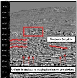
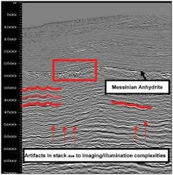
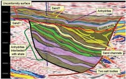
The Messinian of the Egypt Nile delta is comprised of alternating partially eroded thin anhydrite and other shallow marine and fluvial sediments at around 3 km (9,842 ft) depth. The velocity variations in this interval cause serious challenges to seismic data quality because it is difficult to build an accurate velocity model that accounts for all distortions the waves encounter. These complex formations have fast velocity anhydrite and slow velocity channel fill, plus large lateral and vertical structural variation. Complex, short-wavelength velocity features degrade the image and lead to scatter, attenuation, generation of complex multiple diffraction noise, and variable illumination.
Recent multi-azimuth seismic data over this area shows that multiple diffractions have been suppressed, and that illumination and signal-to-noise ratio has improved (Keggin et al., 2006). However, building an accurate velocity model for depth imaging remains a challenge.
Methodology
Getting an initial velocity model for imaging below Messinian requires the following steps:
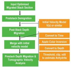
1. Start with an optimum prestack or poststack time migrated stacked section for the area of interest
2. Follow by demigrating this migrated stack section to obtain a zero-offset unmigrated seismic section
3. Poststack depth migrate with an initial model based on a simple V(z) velocity gradient hung from the seabed or time migration velocities converted to depth.
This workflow produces a seismic section approximately consistent with the processing depth at the top of the Messinian in order to resume estimating the thickness below it. Better yet, use an alternative version of this model after one pass of tomographic updating to remove unwanted variations from the starting velocity model.
In both cases it is important to exclude velocities associated from the Messinian anhydrite. They will be incorporated later.
The next step is to apply colored inversion (Lancaster et al., 2000) to the migrated stack in the time domain and then convert it back to the depth domain. This generates an acoustic impedance section in depth that then is related to velocity of the Messinian. Then estimate the thickness of the spatially variable anhydrite layers as well as interleaved sediments using this inverted data with a series of thresholding and automatic editing techniques. The resulting data cube estimates the physical position of the anhydrite layer (denoted as ones) as well as interleaved sediments (denoted as zeros) in depth consistent with the velocity model used for migration. Now assign appropriate velocity values to the intervals and merge the resulting volume with the above migration velocity model.
The next step is to prestack depth migrate the input data to improve and update the direct estimation of the anhydrite layer. Several iterations of tomographic update should suffice for the model to converge to an optimum solution.
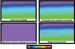
This was applied to a 150 sq km (58 sq mi) subset from a 3D survey of the Egypt Nile delta. Figure 1 compares the following:
- A. Starting V(z) velocity model hung from seabed
- B. Tomographically updated velocity model down to Messinian layer
- C. An estimation of anhydrite layer from the acoustic impedance inverted stack
- D. Anhydrite velocities merged into tomographically updated velocity model.
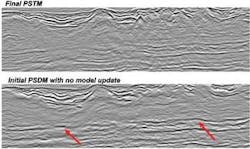
Figure 2 compares an acoustic impedance section on the left and the anhydrite obtained from that. Most of the anhydrite has been captured fairly well except where layers become extremely weak or discontinuous. Further iterations of tomographic updates using the method in Tanis et al. (2003) would help heal the effect of the discontinuities associated with this layer. The use of stacks from recent multi-azimuth seismic data collected over the this area, rather than data from a single-azimuth survey as used here, would improve the accuracy of modeling anhydrite as the stacking response from multi-azimuth data results in a less noisy dataset (Keggin et al, 2006). Figure 3 shows the prestack depth migrated section with the new model that includes the anhydrite layer compared to the prestack time processing.
null
The PSDM section removes some undulations on the stack and improves image continuity. Additional iterations of migration and tomographic updates that includes updating the anhydrite layer as well as pre-Messinian section should further improve the image.
Acknowledgements
The authors thank BP Egypt, RWE Dea, and other partners for permission to publish data, and also Petr Jilek and Mark Sweatman of BP for their contributions.
References
Keggin, J, Benson, M., Rietveld, W., Manning, T., Barley, B., Cook, P., Jones, E., Widmaier, M., Wolden, T. and Page, C. 2006, Multi-Azimuth towed streamer 3D Seismic in the Nile Delta, Egypt: 76th Annual Conference and Exhibition, SEG, Expanded Abstracts.
Tanis, M.C., Etgen, J.T. and Shah, H., 2003,, High resolution velocity model building through iterative migrations in the Caspian Basin: 73rd Annual Conference and Exhibition, SEG, Expanded Abstracts.
Lancaster, S., and Whitcombe, D., 2000, Fast-track ‘coloured’ inversion: 70th Annual Conference and Exhibition, SEG Expanded Abstracts.
