The Thunder Horse challenge: Optimize perforating performance in an HP/HT deepwater well
L. Sabbagh - Schlumberger
D. Blalock, H. Leung - BP
J. Melvan - Orbis Engineering
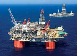
The Thunder Horse field in 6,000 ft (1,829 m) of water in the Gulf of Mexico, has stacked consolidated sandstone reservoirs at 20,000 to 30,000 ft (6,096-9,144 m) subsea with pressures of 14,000 to 18,000 psi (96.5-124 MPa), temperatures of 190 to 270° F (88-132° C), and mean rock strengths of 4,000 psi. The wells normally are completed with a 7-in. (17.8-cm) liner and perforated with 3 3⁄8-in. (8.6-cm), high-shot-density (HSD) wireline guns with deep penetrating charges. However, as a result of drilling problems in one well, a 4 ½-in. (11.4-cm) production liner was cemented in the 8 ½-in. (21.6-cm) hole. The tight tolerance between the fired guns and the pipe ID created an additional challenge. After extensive analysis, design, and yard testing showed the well could be perforated safely using 2 7⁄8-in. (7.3-cm) HSD guns with new enhanced deep penetrating charges that could deliver better perforation performance than the original gun system. The results from the well’s cleanup program indicated an even better perforation efficiency than observed earlier.
This BP-operated deepwater development with partner ExxonMobil is in Mississippi Canyon blocks 776, 777, 778, and 822. The field contains hydrocarbons in two main structures: Thunder Horse North (THN) and Thunder Horse South (THS). In 1999, THS was discovered by the MC778-1 well, and THN was discovered in 2000 by the MC776-1 well. Both structures consist of dip closures near a salt wall.
Well history
The well was drilled originally in 2001 and later sidetracked in the 13 3⁄8-in. (34-cm) casing to maximize reservoir access. The sidetrack and completion were from Transocean’sDiscoverer Enterprise, a fifth-generation dynamically positioned drillship.
The well had to be sidetracked again during deeper drilling because of stuck drillstrings. Drilling also was delayed by weather problems such as loop currents, tropical storms, and hurricanes, all common in the GoM. While running the 7-in. (17.8-cm) production liner, it became stuck and was set high above the top of the reservoir. The best available option was to case the 8 ½-in. (21.6-cm) hole across the reservoir with a 4 ½-in. (11.4-cm) contingency liner. After successful placement of the 4 ½-in. liner, the well was released to the completion team. The completion team, who had already prepared for a 7-in. liner completion, had to redesign and prepare equipment for the new 4 ½-in. liner size within a relatively short time. Once under way, the actual completion operations went essentially as planned.
Original perforation plan
The well’s initially proposed completion design was to set a 7-in. 38 lbm/ft casing with a drift diameter of 5.875 in. (14.9 cm) across the reservoir. Under these conditions, the selected perforation gun system for this job was a 3 3⁄8-in. (8.6-cm) HSD gun loaded with deep penetrating charges at 99° phase and six shots per foot (spf) shot using 3 3⁄8-in. perforating hardware. This gun system was projected by perforation simulation software to deliver a mechanical skin factor less than one. The 3 3⁄8-in. gun system has a published gun swell (OD) of 3.66 in. (9.3 cm); this gives approximately 2 in. (5.1 cm) of casing clearance. When the drilling approached total depth and the LWD data were available, engineers could figure roughly how long the perforation interval would be. Consequently, the required 3 3⁄8-in. guns with the necessary hardware and backup were ordered. But, because of the drilling complications explained earlier, those guns could not be used inside the 4 ½-in. liner.
The challenge
The pay sand was originally drilled with an 8 ½-in. bit and a final average caliper of 9 in. (22.9 cm). Because of drilling problems, the open hole in the pay zone was exposed to mud for an extended period. Finally, it was cased with 4 ½-in. 17 lbm/ft casing with a drift diameter of 3.7 in. (34.8 cm). This mandated that a smaller OD gun system be used, even though the cement sheath around the casing increased to over 2 in. The small liner generated a lot of debate amongst the various design disciplines. The team’s greatest challenge was to deliver a good completion, minimize operational risk, and maximize well performance, given the wellbore changes. This forced a re-evaluation of the perforating system while the completion operations were being started.
Gun systems evaluated
Perforation modeling analysis was performed on the characteristics of the five HSD gun systems with various explosive loads, including 3 3⁄8-in., 2 ½-in., and 2 7⁄8-in. The characteristics included charge explosive load, phasing, formation penetration, and enhanced hole diameter. The first gun size, 3 3⁄8-in., is the original gun system planned for the 7-in. liner. The remaining gun systems are options which include deep penetrating charges and new systems with enhanced deep penetrating charges.
The perforation performance modeling results on the same gun systems clearly indicated that the 2 7⁄8-in. gun system with the new enhanced deep penetrating charge could deliver skin factor and productivity index values closest to those anticipated with the original 3 3⁄8-in. gun system with the deep penetrating charge.
A risk analysis was performed on the following in keeping with best practices:
- Gun size - Because of the large maximum outside diameter of the 3 3⁄8-in. gun system, it could not be considered realistically for use in the 4 ½-in. liner
- Perforating hardware - The hardware includes the cable head, fusible weak point, and firing head
- Gun shock and formation surge effects - In deep and/or high-pressure applications, a large gun shock is generated in both an up and down direction when a hollow carrier gun is instantaneously flooded by completion fluid at the instant of firing
- Perforation skin damage - When the reservoir engineers looked at the models for conditions of the 8 ½-in. open hole, given the duration of mud exposure, they calculated that the skin effect could have doubled, approaching a two digit value, and that the productivity index was significantly below the desired value.
Risk considerations, actions
Initially, the team preferred to use the 2 ½-in. HSD gun system as a measure to mitigate the effects of the initial reservoir fluid surge and to evaluate the potential shock (perforating in a closed chamber). The completions operations team believed the 2 ½-in. HSD with the enhanced deep penetrating charge was the most conservative option but accepted the subsurface team’s desire to use a 2 7⁄8-in. HSD gun system with deep penetrating charge for increased well performance. A system integrity test (SIT) and test shoot were performed to qualify the 2 7⁄8-in. system.
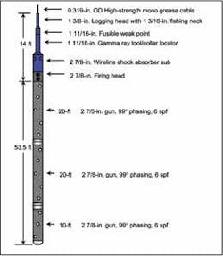
With the tests and analyses complete, the team decided it was operationally acceptable to use the 2 7⁄8-in. HSD gun with deep penetrating charge, a 2 7⁄8-in. wireline perforating shock absorber, and a 1 11⁄16-in. gun gamma ray tool and perforating head. The next step was to determine if more options were available to restore well performance to levels near those with the originally planned 7-in. casing.
Perforation modeling showed that the 2 7⁄8-in. HSD gun with the new enhanced deep penetrating charges would restore the desired well performance. The team was aware of added risk using the new charges and requested assurances that the use would not endanger well operations. Gun shock modeling comparison of the deep penetrating charge used on earlier completions versus the new enhanced deep penetrating charge was performed and showed little difference between the two.
An SIT and test shot were performed successfully at the service company’s perforating center test well. The 2 7⁄8-in. HSD gun system with the enhanced deep penetrating charge (99°, 6 spf) run with 1 11⁄16-in. perforating hardware was qualified for 4 ½-in. casing as per Thunder Horses best practices. The purpose of the SIT was to:
- Confirm the published gun swell data (maximum OD after firing)
- Obtain experimental gun shock data from tension and wireline shock absorber crush-element deformation
- Qualify 1 11⁄16-in. perforating hardware with 50 ft of 2 7⁄8-in. guns
- Qualify 1 11⁄16-in. fusible weak point with 50 ft of 2 7⁄8-in. guns
- Recap procedure for lifting and laying down the guns.
Finally, in an effort to ensure successful execution of the perforating program, all hardware for this job was specified by the operating company for “critical wells,” which included complete dimensional verification and material certifications.
Job execution
This was a very demanding and challenging job comprising a large total vertical depth, 45° deviation, 13 gun runs, 15,000 psi pressure control, and work conditions high in the derrick inside a coiled tubing tension lift frame from a floating vessel:
- Number of runs: 13 wireline perforating runs
- Casing size: 4 ½-in. casing with a drift ID of 3.7-in. (9.4-cm)
- Gun size: 2 7⁄8 in.
- Well deviation: 45°
- Reservoir temperature: 240° F (116° C)
- Completion brine weight: 14.1 lbm/gal
- High-strength cable (5/16-in.): 7,500 lbf safe working load; 11,742 lbf breaking strength
- Normal surface tension: 5,000 lbf
- Rig wireline BOP: On top of surface tree (15,000-psi flowhead)
- Rig-up guns: Inside coiled tubing lifting frame
- Pickup and laydown guns: Using rig tugger lines
- Total time (rig-up to rig-down): 8.6 days
- Average operating time per run: 9.2 hours.
Two E-line crews worked on a 24-hour basis. E-line crew shift changes were staggered with respect to the rig crews’ shift changes to avoid loss in communication or continuity. The projected time per run was 13 hours, but as the rig crews became accustomed to the detailed gun handling operations, the surface time for swapping the guns was minimized with the final runs being performed in eight hours, with an average cycle of 9.2 h/run for the 13 gun runs.
The executed perforating program was as follows:
- Run 1: 50-ft gun with a 5-ft blank in the middle
- Run 2: 30-ft (9-m) gun with two memory gauges to record reservoir pressure, because no formation testing tool was run. These two runs were followed by 24-hour flow period No. 1 and an 18-hour initial shut-in period (pressure buildup one).
- Run 3: 30-ft gun
- Runs 4, 5, and 6: 40-ft (12-m) gun each
- Run 6 was followed by a 16-hour flow period
- Run 7: 45-ft (14-m) gun
- Run 8 and 9: 50-ft gun each
- Run 10: 45-ft gun
- Run 11: 10-ft (3-m) gun
- Run 12 and 13: 30-ft gun each
- Perforation run 13 was followed by a 26-hour flow period and a 24-hour pressure buildup period.
The entire job was executed according to plan. Preliminary planning with attention to operational details was the foundation for a solid plan. Close teamwork between the rig crews, the wireline crews, and wellsite supervision lead to execution of the plan.
Perforation job outcome
The perforation job exceeded expectations. The total operating rig time for the 13 perforation runs was 122 hours, as compared to the planned 169 hours. This translated into an efficiency of 138% compared to plan and represented significant cost savings.
Flow period No. 1 provided the needed vertical and horizontal permeability, skin factor, and the Kv/Kh information. Ultimately, the well was flowed over three separate flow periods with three separate buildup periods.
The final calculated mechanical skin factor was less than two, in line with the planned 3 ⅞-in. gun performance, and exceeded expectations because of the well’s final geometry.
The flow potential of this well is significantly higher than the previously produced rate, but it is limited by the tubing erosional velocity. As a result of the team’s effort, use of the largest gun possible (2 7⁄8-in.) with the given 4 ½-in. casing did not result in additional mechanical skin damage.
Most importantly, the job was executed safely and professionally.
Acknowledgments
The authors thank the management of BP, ExxonMobil, Schlumberger, and especially the personnel at the Schlumberger Houma Offshore Cased Hole District for their support in preparing and executing this successful job and for the opportunity to present the results. We also acknowledge contributions by Harvey Williams, Schlumberger, who performed the gun shock modeling; and by Wes Black and Patrece Clay, BP; Lynn Saucier, Clover; Tony Meszaros, David Kennedy, and Bruce Tarantola, Schlumberger, who jointly provided leadership, support, supervision, planning, and job execution.
Editor’s Note: This is a summary of the SPE 113727 paper presented at the 2008 SPE Europec/EAGE Annual Conference and Exhibition held in Rome, Italy, June 9-12, 2008.


