Bjorn Melve
Perry Nice
Statoil
Mike Posson
Duoline Technologies
Statoil has developed internal specifica-tions for the use of downhole tubing with composite material liners in the North Sea after an extensive test and pre-qualification program based on results from a well in the Norne field.
null
The Norne oil field development in the North Sea originally planned to inject untreated "raw" seawater to save topside space and investments. The conventional selection for downhole tubing was a costly CRA (corrosion resistant alloy) to cope with the corrosive injection water. Economically priced carbon steel using a composite material liner appeared to be a viable alternative.
A Duoline Technologies system seemed be the best solution for water-injection wells, with proven onshore applications but limited experience under the conditions in a North Sea well. The corrosion properties of the glass fiber epoxy liner suggested that the system would work with relation to variations in water and fluid properties.
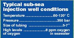
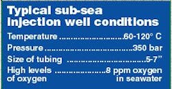
Fiberglass liners in downhole tubing have been used since the early 1970s in onshore wells in North America. The technology was initially driven by the challenge to ensure longer lifetime of the tubing in injection wells. The system's principle is a long, thin-walled glass fiber epoxy liner that is used as a corrosion resistant alternative for fluid transport in multiple industries. Composite lined tubing had been used for water injection in several Statoil fields. The Yme field was abandoned in 2001, and the state of the tubing with the liner was extracted and evaluated after five years service. The tubing had been used for injection of raw seawater (water without oxygen removal) at bottom hole temperatures up to 110° C (220° F) and pressures up to 350 bar (5,000 psi). The liner properties and especially the exposed surface showed some degradation, but the overall mechanical properties were within acceptable limits. The results supported the use of composite lined tubing for water injection in North Sea well conditions.
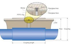
The liners are inserted in the steel tubing and locked in place with a cement layer that is filled in the annulus. The ends of the glass reinforced epoxy liner are covered with flares for mechanical protection against well operations. A corrosion barrier ring protects the couplings and is adaptable to various coupling and connector types, both standard and premium (gas tight connections). Typical lengths of the tubulars are 10-12 m. Some important facts:
- The liner is not chemically bonded to the carbon steel, but is restricted in movement by the cement and the barrier rings at each connection
- The corrosion barrier ring and flare system are not completely gas and fluid tight. This allows for some small amount of corrosive fluid and gas to enter into the connection area and under the liner
- The cement layer is already present with a high pH that quickly stops corrosion, since the fluids are not replenished
- The annular pressure is in equilibrium with the bore so no new gas or fluids can enter
- The fact that there is some communication also prevents large differential pressures from building up behind the liner. The risk for collapse of the liner is limited
- Use of low cost carbon steel
- Corrosive resistance of glass fiber epoxy
- The steel takes all loads.
Test program
Statoil conducted a three-year test to qualify the composite lined tubing for North Sea conditions. The test program included:
- Several combinations of internal pressure with bending and axial forces
- Fatigue testing of connections
- High injection rates with water speeds up to 15 m/sec
- Rapid decompressions of pressures at elevated temperatures
The product was qualified for typical water injection, both produced water and raw seawater, and an internal specification was written for the application.
The well depths varied from 3,000-5,000 m. The connection type for all wells was NS-CC- FGL (Nippon Steel Casing threads modified for glass fiber liner). The connection used a new design modified from a connection developed for internally epoxy-coated tubulars. None of the injection wells reported problems relating to the composite material liner after they have been put into service.
Because the Yme field was to be in service for only five to six years, it presented an opportunity to examine the condition of the liner after years of real exposure.
null
Functional requirements
All the global loads (tension, pressure, bending) are handled by the external carbon steel tubing. Compared to other uses of composite materials, such as low/high-pressure piping, no long-term loads needed to be carried by the liner. The primary requirement for the liner system was to:
- Provide a barrier to prevent open circulation of corrosive fluids and gases from the bore to the inside of the carbon steel wall throughout the lifetime of the tubing string
- Provide sufficient ring stiffness to prevent collapse of the liner and keep the liner in contact with the mortar and steel wall
- Withstand normal well operations such as wireline and coiled tubing. Some restrictions on tooling can be imposed
- Maintain hoop-bending strength of the material.
The long-term stiffness and strength can be determined by accelerated aging at elevated temperatures following Arrhenius testing. However, the recommended method of evaluating strength and stiffness is testing ring segments by bending. The main challenge for the liner is collapse, so the hoop properties need to be evaluated.
Due to uncertainties in how to determine the stiffness (modulus) for curved specimens, the change in stiffness can be reliable only on a relative scale. That means the reference and exposed materials must be tested with exactly the same parameters (span, loading rate, temperature).
null
Yme injection well
The Yme well was complicated with a dual completion for simultaneous injection of water and gas, necessary for pressure support in the reservoir. The water came from the platform through a 4.5-in. composite lined section above the safety valve (220 m with lined tubing). The main part of the well (3,300 m) was made up with composite lined 7-in. tubing (7-in. OD, 29#, Grade L-80). The composite material liner had a nominal thickness of 2.5 mm.
The estimated bottom hole temperature was around 110° C. This temperature is rather high for continuous water exposure for glass fiber reinforced epoxy. At the time of installation, the cold injection water was expected to help slow down potential degradation. For operational reasons, the tubing was exposed to higher temperatures than expected because water was not injected for periods of two years. This meant that the average exposure temperature of the liner was higher than expected in the design phase.
In the same well, the 3.5-in. tubing at the bottom of the well was wrapped externally with glass fibers. This was done to prevent external corrosion on the gas tubing in the water injection zone. The tubing was not pulled, so the status after exposure is unknown.
Due to the low permeability of the intended gas injection structure, some perforation had to be done in the bottom of the well. The perforation gun got stuck, and subsequent wireline operations resulted in an additional 21 runs. The well was used for raw water injection for a few months, but was finally converted to a produced-water injector.
System inspection
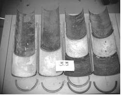
The tubing string was pulled and the joints inspected at Statoil's offshore base in Stavanger. Although the general status impression of the tubing was good,. a substantial amount of deposits were found in the joints. Both the pin and the coupling ends of selected joints taken from various locations in the well were sent for further laboratory investigation. Deposits on the surface displayed a grayish top layer and a reddish inner layer. This is consistent with the operation of the string, as it was first used for water injection from a carbon steel system with a lot of corrosion products, and then produced water, which can lead to the deposit of other salts. Diffraction analysis of the deposits confirmed that this was the case.
The PTFE seal ring had been pressed into the bore at some locations. This problem, observed during completion of the string, was from too much dope on the threaded connections before the box and pin ends were made up. It was considered remarkable that the tubing was in good condition, even with the deformed rings. This observation demonstrates the robustness of the system. In later completions, the procedure was changed and every joint drifted to avoid such problems.
Another observation was the liner flare had been eroded almost flush with the liner in some locations. However there were no signs of corrosion of the steel under the eroded areas.
Even though the flare had been eroded by the wireline operations, no evidence was found of actual damage of the liner itself. The only evidence of wear on the liner was thin erosion lines and discoloration from the rust water that had been injected. The unexposed side of the liner still looked almost new.
The liners were cut into 20-mm-wide strips in the circumferential direction. A loading span of 108 mm was used for three-point bend testing with a loading rate of 1 mm/min. The results were compared to similar test data on unexposed material from a different batch, but the reference point was not absolute because reference (unexposed) material from the batch that went into the well was not available. Results were above the proposed reduction in stiffness as an acceptance criterion.
From the test results, it is reasonable to conclude that the bottom joint was more degraded than the rest. One of the factors that supported the use of this system for the Yme field was a presumption that the injection of cold water would reduce the operating temperature and cool down the reservoir with time. The well was operated with raw water injection for a short while, but the operating temperature for most of the five years had been close to reservoir temperature of 100-110° C.
If the environment had been hydrocarbons with a small water cut, the observed degradation would have been expected to be much lower. The water is the most aggressive component for the epoxy and the bonding between glass fibers and epoxy.
