Full waveform inversion improves subsurface models
Jerry Kapoor
WesternGeco
Full waveform inversion is providing the E&P industry with ever-more detailed images and models of the subsurface that can make exploration, development, and production more efficient and reduce drilling risk.
One of oil and gas exploration's greatest challenges is to image reservoirs with sufficient accuracy to pinpoint oil and gas deposits and to reduce drilling risk. Surface seismic surveys measure the two-way travel time of acoustic waves to subsurface reflectors. To convert travel time to depth requires knowledge of the velocity of sound, and its travel path, through all the layers above and around a particular reflector. While converting time-domain information into a reliable depth model of the Earth remains an inexact science, advances in data processing technology are delivering continuous improvement.
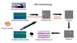
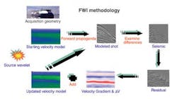
General workflow deployed on FWI projects.
Technological advances have delivered success in the exploration of complex structures such as deepwater subsalt reservoirs in the Gulf of Mexico, South America, and West Africa. However, despite significant progress in recent years, there remain many challenges to earth model building and imaging in the most complex geological environments. Increased complexity in imaging challenges, combined with ever-increasing computing capacity and cost-efficiency, has driven a change from traditional ray-based methods to waveform methods for model building and imaging.
The seismic industry has moved to using two-way wave equation imaging algorithms commonly known as reverse-time migration (RTM), especially in areas of complex geology. It has become increasingly obvious that to obtain full benefits from these advanced imaging algorithms requires development of an accurate velocity model. Inversion is a mathematical process by which an earth model is generated that is consistent with the measured surface seismic data and other available controls such as well log and vertical seismic profile (VSP) data. The model includes the depth and thickness of subsurface layers and their acoustic velocities, optionally including azimuthal anisotropy.
Full waveform inversion (FWI) has long been considered the next logical step in deriving detailed velocity models. The availability of long offset datasets with high signal-to-noise ratio and broad bandwidth, particularly including low frequencies, now allows FWI to build high-definition velocity models that can enable more detailed imaging of reservoirs. An accurate earth model is essential to any successful depth imaging project. FWI is an advanced velocity model building process that uses the full two-way wave equation and overcomes the limitations of existing methods that use a ray-tracing approach to distribute velocity errors within the model.
Full waveform inversion
FWI, based on the finite-difference approach, was introduced in the time-space domain around 1984. Inversion can also be implemented in the frequency domain. Within the last five years, 3D FWI has been applied to several datasets from both offshore and onshore. These projects demonstrate that FWI can be used for velocity updates if the acquired data have enough low frequencies and long offsets. In particular, the shallow part of the model can be enhanced significantly with FWI, which can result in an improved depth image at reservoir level(s).
One difficulty with FWI is convergence to the local minima. To avoid converging to a local minima requires a starting velocity model that bridges the gap between the low frequencies and long offsets acquired in the data. Generally the starting model is a smoothed version of a tomography-derived legacy model calibrated with well logs, VSPs, gravity, magnetotelluric, and other available measurements. Such tomography-derived models are not immune from convergence to local minima, hence the need to smooth such models.
Successful results from FWI first require a feasibility study to ensure that an optimum combination of acquisition parameters, starting velocity model, and data with appropriate preprocessing are available. Modern acquisition designs that deliver low (2-3 Hz) frequencies, long (12-20 km/7.45-12.47 mi) offsets, and data from a full range of source-receiver azimuths can relax the requirements of the starting velocity model. Starting with a simple smooth velocity model without local minima is desirable; however, older acquisition designs lacking in low frequencies, long offsets, and azimuths require adding detail to the starting model, usually with several iterations of tomography.
Starting data ideally are minimally processed, typically with noise attenuation only, as it is easier to match modeled data with the acquired data if the original waveform of the acquired data is preserved. Early arrival data, rich in refractions and diving wave energy, should be preserved to allow for the low-frequency update of the velocity model. Care must be taken to not mute out these early arrivals - not only for FWI but also for imaging with RTM.
A 3D time-domain TTI anisotropic acoustic version of full waveform inversion has been implemented using the two-way wave equation with an elastic correction factor to model seismic data using an initial best guess of the earth model. This can be a depth model from a previous processing effort and/or calibrated to well logs and any other seismic or non-seismic measurements. Seismic waveform inversion is based on minimizing a cost function that measures the difference between the calculated and acquired data. To minimize the cost function, several forward modeling and residual back propagations are required to gradually update the velocity field. The optimized time domain approach in the shot domain makes waveform inversion feasible for large 3D surveys.
FWI iterations
Important steps are to quality control (QC) the process between iterations of FWI versus the starting velocity volume, and to check whether or not the modeling produces cycle skipping with the collected data. The traditional approach to QC of FWI is through comparison between the simulated and the observed data, usually in the shot domain. This is relatively easy for 2D seismic data; however, 3D surveys have considerably more shots and it can take a great deal of time to page manually through and correlate thousands of shots across the 3D area. So, QC tools must be partially automated to complete comprehensive reviews in a timely fashion, especially between iterations. A method has been developed whereby iterations can be QC'd in production without adversely impacting time and human efforts. Three attributes are used to control the FWI iterations: the cross correlation; the root-mean-square (RMS) amplitude; and the time shift between the predicted and the observed data volumes. The objective of QC for convergence criteria is to maximize the cross correlations, minimize the RMS amplitude, and minimize the time-shift maps across the survey area.
FWI results
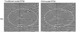
FWI has been applied to datasets from all of the world's major oil producing areas, including the Middle East, Far East, North Sea, Gulf of Mexico, and the Atlantic Margin. Most of the projects performed by WesternGeco have involved data from the Gulf of Mexico, including approximately 65,000 sq km (25,097 sq mi) of wide-azimuth and full-azimuth long-offset data, much of it acquired with the company's dual coil technique. In the wide-azimuth example shown, the RTM image produced from a velocity model developed with FWI shows improved structural closure and enhanced detail in the sediments compared to the image from a model developed using tomography. The ability of FWI to delineate salt reflectivity, starting with a sediment velocity model derived from a conventional tomography approach, reduces the manual effort required to interpret salt geometry.
Leveraging successful Gulf of Mexico projects, FWI technology has been deployed in various geologic settings around the world including onshore data from the Middle East and China. Parameterization varies significantly between different geological provinces to suit the geology and acquisition parameters. In all of the these projects, improvements have been seen in the detail of velocity models produced by FWI compared with those from conventional ray-based tomography.
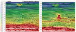
In the example shown from the North Sea, which used ocean bottom cable data, FWI successfully delineated a shallow velocity feature caused by a channel. Conventional tomography did not identify this feature, which had to be manually inserted in the model. It also failed to identify the rapidly varying velocity of the feature in the center of the data example. Correctly addressing variations like these in the overburden velocity model has a significant impact in improving delineation of the reservoir below.
The example from offshore Australia used conventional narrow-azimuth marine 3D data. It shows the capability of FWI to start with a low-frequency model and iterate to a high-frequency detailed velocity model. Addressing complexities in the overburden velocity model simplifies the structure at the reservoir level below, thus adding credibility to the FWI velocity model.
Conclusions
Although FWI on real 3D data sets is challenging, it is becoming feasible and provides high-definition images and velocity models that reduce drilling risk in a variety of geologic settings. Successful application of FWI is facilitated by modern acquisition designs that deliver low frequencies, long offsets, and a full range of all azimuths. A starting velocity model is required to bridge the gap between the low frequencies and long offsets acquired in the data. Starting from low frequencies, FWI can iterate to high-frequency models. Adequate QC between iterations is required to ensure convergence. Current applications are acoustic, but elastic FWI is also a possibility.


