Don Francis
Special Correspondent
In the upstream oil and gas industry, record-setting performances of various sorts are frequently touted. But, because of the interlocking nature of all the components of this highly complex enterprise, it is difficult to ascribe success exclusively to just one part.
Achievements of systems—in this case, drilling systems—are easier to measure. Things like footage drilled over time are important, of course, but one metric in particular is arguably the most important of them all: reservoir exposure to a single wellbore.
Extended-reach drilling (ERD) has been around for many years, but the tempo of technical developments is quickening in response to the ever-growing challenges the industry faces in a world where the "easy oil" has already been found.
ERD shines in maximizing reservoir exposure in a single wellbore. The definition of "extended-reach drilling" is not set in cement, but many consider it as drilling a well with horizontal displacement at least twice the true vertical depth.
Other definitions of ERD wells include wells having horizontal displacements greater than twice the true vertical depth, yielding inclination angles exceeding 63.4°; wells that approach the limits of achieved by the industry in terms of horizontal displacement; and high-angle directional wells that approach the capabilities of the contracted rig.
A degree of difficulty is also involved. Generally, shallower reserves are more difficult to access by ERD methods.
Typically, the ERD limit is reached when one or more of the following occurs:
- The hole becomes unstable, due either to time exposure, geomechanical interaction, adverse pressure differential, or drilling fluids interaction (or incompatibility). The onset of these conditions usually results in the sudden increase of torque and drag in the drillstring not related to dogleg severity (DLS) of the hole or the length of the drilled section.
- The drillstring no longer travels to the bottom of the hole due to excessive drag. This is differentiated from the preceding in that this effect is not related to the friction factor, which remains unchanged. Instead, it is related to the cumulative length drilled along with the DLS of the hole as drilled.
- When rotation is used to overcome friction and advance the drillstring, such as in rotary steerable application. The limit is reached when you reach the torque capacity of the tubulars.
The most often-cited purposes of ERD are to reach a larger area from one surface drilling location, keep a well in a reservoir for a longer distance in order to maximize its productivity and drainage capability, and/or drill and produce the reservoir from a remote location, to avoid hazards.
With these advantages come challenges. One of the most fundamental is mechanical loads on the drillstring, an area where nontraditional materials and new ideas are showing promising results. Hole cleaning and managing downhole pressure are also critical, and new ideas are addressing these problems as well.
Other important technologies include the use of rotary steerable systems (RSS), measurement-while-drilling (MWD), and logging-while-drilling (LWD) tools. It is not an overstatement to say these technologies make ERD possible.
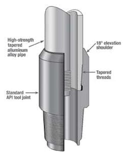
(Image courtesy Alcoa Oil and Gas)
Well planning considerations
For some ER wells, careful well planning and existing drilling practices are sufficient to avoid problems such as wellbore instability, lost circulation, and stuck pipe. However, results from several studies show that when well step-out ratios increase, some operational practices developed while drilling conventional wells become inadequate to cost effectively deliver the ER wells. Careful planning alone cannot always prevent drilling problems.
ERD well profile design is not a simple geometric curve. It is an integrated process that requires an optimum well path profile with respect to torque and drag. Two main principles should be obeyed when planning an extended-reach well: minimizing torque and drag, and minimizing well length.
McClendon and Anders (1985) described the use of the catenary well plan method for directional drilling. A modified version of this method was used with success to drill some early ERD and horizontal wells in the North Sea's Statfjord field. The method was mainly used to reduce torque and drag by reducing the wall forces in the build-up section. This was done in the top part of the hole where the drill pipe tension and side loads were highest.
As is the case with all drilling operations, detailed engineering preplanning is critical to successfully drill ERD wells. It is crucial to be able to accurately predict the following parameters under actual downhole conditions:
- Static and dynamic temperature profiles in the well
- Hydraulic pressures
- Annular pressure loss
- Equivalent circulation density
- Mud rheology.
Nontraditional drillstring materials
Advances in drilling and drill pipe technology for complex horizontal and ERD well profiles are continuously pushing for extended capabilities of the drillstring. Demands for performance include increased tensile strength-to-weight ratios and high-torque connections to overcome frictional drag forces and to achieve improved hydraulic performance, rate of penetration, control of well trajectory, and optimal hole cleaning.
Alcoa Oil and Gas reports that in one case, a well was drilled from a small production platform with a workover rig using a drillstring that combined 57⁄8-in. steel pipe with 2,500 m (8,200 ft) of 57⁄8-in. of its alloy drill pipe. The operator was able to drill 22% farther (more than 1,000 m, or 3,280 ft) than with steel drill pipe only (due to top drive limit).
The lighter drillstring increased pipe storage capacity on the platform, which had limited deck load capability. Increased overpull margin improved the ability to deal with stuck pipe or tight hole conditions, and reduced string stretch at total depth allowed pickup off bottom with the short derrick. This mix of steel and alloy drill pipe can increase the ERD operating envelope of smaller rigs and reduce field development project costs.
Alloy strings can be up to 40% lighter (dry weight) and more than 50% lighter (wet weight) than E-Grade steel drill pipe. Depending on the "blend" of the alloy pipe and steel, drilling depth capacity of an existing rig can be upgraded as much as 100%.
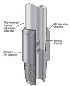
The alloy drill pipe is designed to use standard API tool joints. Tool joints are connected to the drill pipe using a thermal shrink fit technology. This connection uses a proprietary tool joint machined with six modified Acme threads per inch (RH) on a 3⁄8-in. taper per foot. The end of the pipe has a smooth, concentric shoulder, while the rest of the pipe is tapered through the transition zone. The inside of the pipe end of the tool joint displays the threads, the end shoulder, and the counterbore.
After assembly, an interference fit exists between the tool joint and the pipe. The annular section of the tool joint contracts after assembly and provides an additional interference fit. The pipe end is thus firmly gripped by the tool joint, providing a pressure-tight assembly and efficient transfer of tension, torsion, bending, and compression loads between the pipe and working connection.
High-strength steel pipe
High-strength steel grades are a type of alloy that provides better mechanical properties than API carbon steel. Alloy elements are added to the steel during smelting to strengthen it. This eliminates the toughness-reducing effect while increasing the material's strength by refining the grain size.
For ultra-deep or landing string applications, high-grade materials offer additional tensile capacity and impact strength compared to API grades. By using high-strength material to reduce tube body wall thickness, lighter drill pipe joints can be manufactured without compromising mechanical performance.
For complex drilling environments, including ultra-deep and extended-reach wells, deep offshore or high-pressure/high-temperature conditions, Vallourec Drilling Products, for instance, has developed high-strength grades including VM-140 DP, VM-150 DP, and VM-165 DP. High-strength grades are ideal when lighter drill pipe is required to minimize torque and drag in an ultra-extended-reach well. Reducing wall thickness also improves hydraulic programs, making it easier to reach drilling targets efficiently.
Hydromechanical drill pipe
Cuttings buildup can go unnoticed until the well signals problems such as reduced ROP, higher weight on bit (WOB) needs, erratic drilling torque, non-uniform rate of cuttings over the shakers, pipe buckling, high annular pressures, out-of-window equivalent circulating densities (ECD), drillstring whirl, and stuck pipe events. Remedies, which are also flags, include additional wiper trips, sweeps, and long circulating times.
When economically justifiable, mechanical hole cleaning devices (MCD) can enhance performances and are shown to be effective in achieving drilling efficiency gains in long hole sections and highly deviated wells.
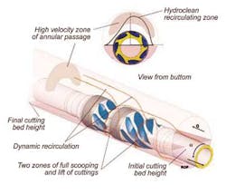
Mechanical hole cleaning devices, such as the Hydroclean tool, developed by VAM Drilling, are used primarily offshore to drill 17½-in. and 12¼-in. directional and deviated hole sections. The tool gradually erodes cutting beds height starting at low RPM by mechanically scooping cutting beds buildup where they cannot be avoided under normal drilling conditions. Cuttings are continuously scooped to a position above the drill pipe and sustained for transport in the high fluid velocity area of the annulus.
Despite worldwide experience with MCDs, few studies have been conducted showing how drilling performances can be improved with an all-inclusive system and measurable key performance indicators. Mixed results have also been reported ranging from total success to disappointments but generally lacking substantiating data. Such outcome is usually predictable because of the need to follow a blueprint from planning to execution. A hole cleaning management system approach for the well is needed, with defined expectations and measurable deliverables on the well site.
Bladed scallops and grooves produce a number of hydromechanical effects to increase cleaning efficiency of the drillstring. A drill pipe joint and heavy weight drill pipe comprise the tool. The tool provides full and immediate degradation of cutting beds while keeping more cuttings in suspension on the high side of hole, where fluid velocities are highest. Hydromechanical hole cleaning is achieved through the combination of three hydromechanical effects.
Scooping. Cuttings deposited on the low side of the hole are mechanically eroded at low RPM, which prevents cutting-bed buildup around the drill pipe.
Recirculation. Once lifted, cuttings are recirculated up to the high side of the hole and above the pipe.
Transportation. Regardless of the energy input exerted on the cuttings during recirculation, they travel only a certain distance and eventually resettle on the low side of the hole due to gravity. A "conveyor belt" has to be established to maintain cuttings transport to the surface.
Dual drillstring
A technique called the Reelwell Drilling Method (RDM) intends to solve the problems of hole cleaning and managing downhole pressure. RDM is the result of a joint industry project (JIP) on ERD aimed at achieving a drilling reach exceeding 20 km (12.4 mi).
RDM uses MPD to achieve ultimate ERD. The method is based on the use of a dual drillstring (DDS), a closed-loop flow circulation system, where drilling fluid flows to the bit via the drillstring annulus, and the return flow to surface is through an inner string. Efficient hole cleaning is obtained because drill cuttings are removed from the wellbore just above the BHA and are transported to the surface via the inner string.
The DDS is a conventional 65⁄8-in. drill pipe where each joint is equipped with 3½-in. inner pipe, with a 3-in. ID. The DDS is handled according to normal procedure on the drill floor. Well control is handled conventionally by circulating a kick up the annulus and by being able to pump down both channels in the dual drillstring. Tests show that the dual drillstring can be cut off by the BOP shear ram.
RDM differs from conventional drilling in its drilling fluid circulation path. For conventional drilling the fluid returns up wellbore annulus; in RDM the drilling fluid returns to surface through the inner pipe of the DDS. RDM incorporates a special top drive adaptor, dual float valve, and flow control unit. Fundamentally, it is based on pumping the drilling fluid into the DDS annulus and transporting the cuttings back to surface inside the inner string, so that the hole remains clean at all times.
Cuttings go up the inner pipe because it is the only return flow path for the system. The well annulus is sealed with a rotating control device (RCD) on top of the BOP.
The system can also provide hydraulic weight on bit (WOB) using a piston. This also reduces buckling potential of the string and enables more precise WOB control.
Accurate pressure control enables drilling within a narrow pressure window. The system avoids dynamic pressure gradients in the open-hole section and the pressure margins remain also at long horizontal reach. The design enables the use of a passive, well-annulus fluid and an active, circulating fluid of different density. The active fluid can be underbalanced. A heavier annular fluid increases drillstring buoyancy and reduces drillstring torque and drag.
Mechanical and hydraulic calculations have confirmed the capability of RDM to drill wells reaching beyond 20 km.
ERD is a critical for breathing new life into mature oil and gas fields. ERD technology will accomplish what would not be possible through conventional directional drilling. Wellbore stability, hole cleaning, and torque and drag are still challenges, but they will be overcome.
