In addition to the low temperatures, typical deepwater conditions are present at the Gjallar ridge including poorly consolidated sediments at the seabed, possible shallow water flow zones, hydrates, and ooze sediments.
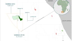
In 1996, Saga Petroleum (now part of Norsk Hydro) was awarded an operator license in four blocks located 400 km north west of Bod;oslash&, in the northern part of the Norwegian sea. Five deepwater areas were opened for exploration drilling in the same licensing round. The water depth is in the range of 1,300-1,400 meters in the area known as the Gjallar Ridge. The weather and current conditions are known to be among the toughest in the world.
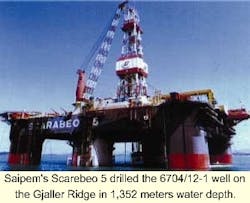
Saga Petroleum completed the drilling of exploration well 6704/12-1 on the Gjallar Ridge in July of 1999. The water depth, 1,352 meters, was the deepest in which a well has yet been drilled in Norway, and, at 400 km from the coast of mid-Norway, one of the farthest yet drilled from land. It was the first deepwater well for both Saga and drilling contractor Saipem. The 4th generation semisubmersible drilling rig, Scarabeo 5, was used to drill the well.
Saga's great hopes for the well were disappointed as no hydrocarbon discovery was made. But although the well was unsuccessful in terms of making a discovery, it can lay claim to be a model as a drilling operation, thanks to a meticulous process of planning and implementation.
Due to undercooled return currents from the Arctic Ocean, the seabed temperature in the area has been measured at -2
Geotechnical conditions
Saipem's Scarebeo 5 drilled the 6704/12-1 well on the Gjaller Ridge in 1,352 meters water depth.
Underlying an approximately 100 meter thick Quartenary sequence starting at seabed, a massive 600-meter thick soft biogenetic ooze sequence was prognosed. This sequence was not penetrated by any of the other deepwater wells offshore Norway, and information was limited to some data from shallow drilling by the Norwegian Deepwater Programme (NDP) and other research programs.
Due to the low density of these sediments, 1.4-1.6 SG, the formation integrity was found to be very low. This is particularly challenging during cementing operations for the 20-in. casing. The requirement is to cement this casing in its entire length with returns to seabed.
The key issues in cement design in an environment like this are low slurry density, rapid strength development and as short transition times as possible.
The quality of the lithological and pressure prognoses is very important to perform safe and efficient drilling operations. Despite the distance of 75 km to the nearest well and the complex geological ties in the area, the pressure and lithological prognoses proved to be very accurate. The main reservoir turned out to be slightly younger than prognosed (Late Campanian versus Maas-trichtian), and the total depth of the well seems to be in the Santonian, while the prognosis suggested a Turonian age.
A special focus was put on the "open-water operations," where the drilling and cementing operations are performed without a riser and returns to surface. This was the most critical part of the well and major failures could lead to re-spud or loss of the well. About 50% of deepwater wells on the Norwegian sector were re-spudded due to problems during the open-water operations. The following major risks for the tophole sections were identified in the planning phase:
- In situ gas hydrates
- Hydrates forming during drilling or cementing
- Shallow gas accumulations
- Shallow water flows
- Unstable fragile sediments causing hole collapse, washouts, and stuck pipe
- Low formation strength.
The drilling and cementing program were designed to accommodate the above risks, and risk-reducing measures were implemented. Also contingency plans were prepared in the event problems occurred. The planning proved to be successful and no major problems were encountered during the tophole sections.
Shallow water flow
Shallow water flow was reported on at least two previous deepwater wells on the Norwegian continental shelf. The shallow water flow resulted in re-spud of the wells and caused additional cost and time spent on the well. For Gjallar, a contingent 16-in. liner below the 20-in. casing was planned in case of hole problems in the shallow and more unconsolidated sections. It would add value if shallow water flow, shallow gas or major hole problems occurred.
Then the 20-in. casing could be set shallower than programmed and the 16-in. liner could be run and cemented to the depth planned for the 20-in. casing. Drilling of the 26-in. hole, running and cementing of the 20-in. casing was performed without any indications of shallow water flow. However, close to total depth of the 17-in. hole section, indications of shallow water flow was observed.
Since full mud circulating system at this stage was established, the mud weight was raised from 1.10 SG to 1.13 SG and the shallow water flow was controlled. No further problems with shallow water flow was encountered on the Gjallar well.
The two critical elements of a cement design to inhibit shallow water flow are early compressive strength development and the thixotropic (gel-strength) characteristic of the slurry. The low temperatures found in a deep-water environment greatly reduced the hydration rate of Portland cement. Because of this temperature effect, steps must be taken to increase the reactivity of a cement slurry used in deepwater applications. Historically, this has taken the form of adding either microfine cement or gypsum to a conventionally accelerated cement design.
Gas hydrates
The oil and gas industry has been aware for several years of problems arising from the formation of hydrates, ice-like structures of water and natural gas, during well-control and drilling operations. The potential for such problems has expanded during recent years with the extension of both deepwater exploration (hydrate formation is favored by conditions of low temperature, high pressure, free-water, and natural gas) and the environmentally favored use of water based rather than oil based muds (water is the main constituent of gas hydrates).
Also, laboratory experiments have identified heavier hydrocarbons, found in oil and gas condensate systems, which can form hydrates and also a new hydrate structure - two factors which may increase the possible hydrate formation region.
Gas hydrates are solid ice-like compounds of natural gas and water. They can exist at temperatures some 20-30 degrees C above the freezing point of water at high pressures. Although hydrates have long been recognized as a problem in oil and gas production operations, the potential for encountering hydrates while drilling is a new phenomenon in offshore operations, owing to exploration activity on the Norwegian sector.
Gas forming into hydrates were reported on another deepwater well on the V;oslash&ering Plateau. The gas was migrating from outside of the 30-in. conductor, and hydrates formed immediately when the gas entered the seabed. The BOP connector was completely frozen up and the BOP could not be disconnected from the wellhead. Therefore the 20-in. and 30-in. casings were cut and retrieved with the BOP still connected to the wellhead. At about 300 meters water depth, the temperature had risen sufficiently to melt the hydrates, allowing the connector to operate.
In the planning phase of the Gjallar well, concerns regarding hydrates were addressed. To prevent hydrates forming and naturally formed hydrates to destabilize during drilling and cementing operations as well as potential well control activities, the mud system had to undergo special studies.
The critical element of a cement slurry design to inhibit destabilization of hydrates is to have as low heat of hydration as possible, and the ability to keep possible free gas from migrating through the cement slurry.
During the Gjallar deepwater operation, no naturally formed hydrates were encountered and no hydrates were formed or destabilized during the drilling and cementing operations.
Project execution
Detailed planning of the Gjallar well started in the Saga drilling department in late 1997 and a small team, which included members of Saipem's rig management, continued the planning process until June 1998. The planning included drilling plans as well as plans for the upgrading of the rig. This planning process terminated in June 1998 because the drilling operation was postponed to 1999.
A new planning process started in February 1999. Important objectives from the start were to reduce costs and ensure a safe operation, both for those involved and for the environment. To optimize the planning process and make further improvements, Saga engaged John de Wardt to apply his lean drilling program. This is a planning method based on giving "ownership" of the project to all involved parties, including the operator, drilling contractor, and service companies - offshore and onshore.
Each party is required to take full responsibility for their input, in the planning and execution phase, in contrast to the usual approach, in which "ownership" is concentrated mainly on those in charge in the operating company. De Wardt's method also puts great emphasis on risk management and contingency planning.
Due to this planning, all the well objectives were met below AFE (appropriations for expenditure) and under planned time. This planning process contributed to the drilling success of the Gjallar deepwater well.
Cementing operations
A deepwater location poses a number of additional challenges to cementing operations, compared with operations on the continental shelf. BJ Services initiated a project in cooperation with Saga Petroleum and Norsk Hydro in 1997, to develop a cement slurry system that could perform as good as possible under these extreme conditions. The already existing BJ Deepsettrademark foam cement system was used as a reference system during the development of the specific cement system used on the Gjallar ridge. As a part of the development project, laboratory equipment in BJ's laboratory in Stavanger, Norway was utilized with a special cooling device allowing thickening times and compressive strength development tests to be performed at temperatures down to -2 degrees C. The final slurry system was developed in the Stavanger laboratory.
The cementing operations on the Gjallar well were a major focus during the planning of the well because of the 600 meters of low-density, low-strength ooze sediments. The density of the sediments was confirmed by MWD to vary between 1.40 SG and 1.60 SG. Special emphasis was placed on performing successful cementing in these zones without loss of circulation.
Conductor installation
A 9-7/8-in. pilot hole was drilled to the total depth of the surface casing section @ 2,162 meters true vertical depth RKB, before the tophole was opened to 36 in. by 42 in. The 36 in. by 42 in. hole was drilled to 1.477 meters true vertical depth (TVD) RKB.
On June 7, 1999, the 30 in. by 36 in. conductor casing was cemented in place from the shoe at total depth back to the seabed at 1,377 meters TVD RKB (1,352 meters mean sea level). A total of 72 cu meters of 1.45 SG gas-tight slurry was pumped through an inner-string, with full returns. Fluorecein tracer and cement was observed on the surface by a remotely operated vehicle. The temperature on the seabed was measured at -2-3
Four hours after the primary job, a planned top-up job was performed, using the Titus top-up tool. Another 10 cu meters of the same cement slurry was pumped. Firm cement was observed as the shoe was drilled out. The conductor casing had a stick-up of three meters and the angle was 0.5
Surface casing
The drilling commenced, and a 26-in. hole was drilled to 2,162 meters TVD RKB. The 600 meters of soft ooze sediments were drilled in this interval without any complications.
The 20-in. surface casing was cemented from the shoe at 2,162 meters TVD RKB to seabed. A one-plug subsea wiper plug system was used to displace 187 cu meters of 1.40 SG lead and 33 cu meters of 1.60 SG tail cement. The remotely operated vehicle observed full returns during the cement job.
The slurries were designed to perform as well as possible in the potential shallow water flow, low density, low formation strength interval. Both slurries had gas-tight properties. The BOP and riser were then run, and the shoe drilled out. A successful FIT test was performed and the drilling of the 17-in. section commenced without delay.
References
Szczepanski, R., Edmonds, B., "Hydrates and Drilling Operations."
Infochem Computer Services Ltd., Brown, N., Hamilton, T., Offshore Safety Division, Health and Safety Executive, UK, December, 1997.
Yousif, M., "Testing of Drilling Fluids for Deepwater Conditions," IIT Research Institute, Westport Technology Center International, December, 1996.
Acknowledgement
The authors would like to thank Saga Petroleum (Norsk Hydro) and partners for support and permission to publish this work.
Authors
Jan Tore Helgesen is District Engineer for BJ Services in Norway and was responsible for the project which developed the deepwater cement slurries. After working onshore and offshore for a drilling contractor, he joined BJ Services in 1997. He holds a BS degree in Petroleum Engineering from the Stavanger University Center.
Flemming Stene was, at the time, Senior Advisor, Drilling in Saga Petroleum, and is now Drilling Superintendent at Norsk Hydro. He has 16 years of experience in drilling technology, design, planning and drilling operations. He has worked with deepwater issues since 1993. He holds BS degrees in Mechanical Engineering and Petroleum Engineering.
Roger Tønnessen was, at the time, Saga Petroleum's technical expert for cementing and completion fluids and is now Drilling Supervisor at Norsk Hydro. He holds an MSc degree in Petroleum Technology and is a PhD candidate at the Norwegian University for Technology and Science.


