Meeting the challenges of a high-ratio, extended-reach horizontal well
Drilling fluid design and implementation is key
S. Ogier
Devon Energy
M. R. Luyster
M. T. Darring
E. Cottrell
M-I SWACO
K. Moreau
W. C. Carlos
Consultant
A measure of difficulty for drilling a horizontal well is the ratio of horizontal displacement (HD) to true vertical depth (TVD). A higher ratio involves a more difficult completion. Typically, this ratio is less than 1:1. However, completions with ratios approaching 7:1 have been documented. When ratios reach 2:1 or higher, the drill pipe is susceptible to excess torque and drag, especially in the case of water-based muds. The challenges for completing a high-ratio horizontal well include reservoir drill-in fluid (RDF) selection and maintenance, wellbore stability, lubricity, torque, cuttings transport, solids control, and fracture gradient.
Improved hydrocarbon recovery in producing horizontal wells has provided the impetus for continued development of extended-reach-drilling (ERD) technology. The relatively high ratio of HD to TVD is one of the many challenges of ERD. As a comparison, the authors calculated this ratio (expressed as HD/TVD) from published well and completion data using record searches of oilfield periodicals. Currently, extended-reach wells (ERW) have achieved ratios as high as 7:1. Published data from the Mineral Management Service in the Gulf of Mexico indicates ratios that range from 0.1:1 to 3:1. Approximately 88% of these wells/completions exhibit ratios less than 1:1. As the HD/TVD ratio increases, the more difficult it becomes to drill, and the complexity also increases. Therefore, more planning and technology is required to mitigate and even eliminate potential drilling problems. For example, ERW are often drilled at angles where frictional forces prevent the drill pipe from reaching bottom under its own weight.
The well
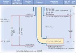
The candidate well is in the Viosca Knoll area of the GoM and was drilled to a total depth of 5,181 ft with a maximum horizontal displacement of 3,760 ft. The target sands range in TVD from 1,790 to 1,868 ft and comprise four separate lobes. This yields an HD/TVD ratio of approximately 2:1.
Based on the sample of data from the MMS, the HD/TVD ratio for the subject ERW plots in the top 2% of wells drilled in the GoM. While this ratio is less than three times that of the highest ERW worldwide, there are nevertheless challenges for drilling and completing at HD/TVD ratios of 2:1 that require careful planning to avert problems.
This gas-bearing reservoir was deposited in the Miocene period and is present throughout onshore and offshore Mississippi and Alabama. Deltaic sedimentation led to the development of the reservoir as a shelf bar. The reservoir was tested in a 1990 completion, but due to economic considerations, it did not produce for any extended period of time.
Conceptual design, planning
The planning team used high-resolution, 2D seismic data in conjunction with 3D visionary software (TDVS) to design the drilling phase/wellpath for this prospect using 3D image projection. The team consisted of geological, engineering, directional, and drilling fluid representatives. TDVS provided resolution of the seismic data that permits and assists the team to systematically define lithological “slices” that should transect the wellbore.
Seismic interpretation showed several pods of sand development at the same vertical level.
The planned casing program consisted of 26-in. drive pipe to 410 ft, 13 3/8-in. conductor to 915 ft, 9 5/8-in. surface casing to 2,883 ft MD/1,886 ft TVD, and 8 1/2-in. open hole horizontal to 5,181 ft MD. The team decided on a 2,300-ft horizontal with a targeted TVD of 1,868 ft and a planned angle of 90.5°.
The operator had prior experience with horizontal wells at similar TVD, with approximately 1,000 ft to 1,100 ft of horizontal length. These represent a HD/TVD ratio of 0.59:1. The current and planned scenario, with a ratio of 2.01:1, more than tripled the HD/TVD ratio this operator had previously designed or completed.
The team performed torque and drag calculations for the proposed drillstring and screen assemblies. This data indicated that a 2,400-ft screen assembly could run to bottom at the projected HD/TVD without the use of rollers. The project team used open hole friction factors (OHFF) of 0.3 to 0.5. However, the casing program required additional string weight greater than conventional drill pipe, necessitating the placement of heavyweight drillpipe (HWDP) in the vertical/low-angle section of the well.
RDF concerns included drilling through significant shale sections (± 700 ft) between the sand bars and enhancing wellbore stability. The need to maintain relatively low drill solids content was of concern, as excess solids can contribute to formation damage and result in poor cleanup. The RDF system was optimized for low-shear-rate viscosity (LSRV) to promote optimum hole cleaning. It was decided that the initial RDF system should have a minimum LSRV of 38,000 sec-1.
Previous experience indicated that periodic additions of biopolymer, shear, and/or temperature would contribute to elevating the LSRV above the desired target of 40,000 sec-1. Another concern included the ability to mitigate losses with a thin and effective filter cake. In addition, as metal-fluid friction was unavoidable, the use of a lubricant would be required. The selected lubricant must be compatible with the RDF system and not grease or interfere with the cleanup chemicals.
As a result of the relatively shallow TVD, a narrow window existed between the pore pressure and the frac pressure. The component elements of the RDF and ECDs would require careful field monitoring to avoid breaking down the sands. The team modeled real-time automated surface data for calculated ECD values since the drilling assembly did not include a pressure-while-drilling (PWD) tool.
Equally important was the ability to clean up the residual filtercake without an acidizing or stimulation treatment once the screens were spotted in the openhole section. They desired a cost-effective treatment. The team could spot treatment using the mud pumps or cementing unit. This would reduce rig time and cost as compared to using a stimulation vessel. The well program included the use of a solids-free RDF to displace the drilling mud from the open hole after drilling to TD to mitigate cuttings beds and excess solids. The breaker would displace the solids-free system from the hole when the screen was in place.
With the completion design established, the team formulated the reservoir drill-in fluid incorporating these fluid objectives.
RDF system
The project team measured and optimized the following fluid properties: LSRV and gels, coefficient of friction (CoF), plastic viscosity (PV), carbonate solids loading and its effect on modified high-temperature high pressure (HT/HP) fluid loss, and density. The goal was to promote good hole cleaning, inhibition, lubricity, a relatively stable and low PV that, in turn, yielded lower ECDs, and minimal concentration of bridging solids.
The team decided on a 2,300-ft horizontal with a targeted TVD of 1,868 ft and a planned angle of 90.5°.
Low bridging solids concentration in the RDF is significant in promoting more efficient cleanup and yields a lower PV, which contributes to low ECDs. Low ECDs enable drilling the length of lateral safely between pressure limitations of reservoir pressure and fracture pressure.
The team selected NaCl brine as the base fluid for the RDF system because it is cost-effective, inhibitive of formation shale, compatible with all components of the RDF system, and meets the density requirements. They engineered bridging solids to minimize both fluid loss and volume required.
The team performed relative fluid-loss tests to confirm the calculated carbonate blend. While RDF No. 4 did not exhibit the lowest fluid loss of the systems tested, other RDF systems with lower spurt loss did not contain a lubricant. The team considered a lubricant essential for reducing friction.
The rheological properties of selected RDF systems indicated that RDF No. 4 exhibited excellent LSRV, PV, and fluid loss properties even after simulated aging. As stated earlier, the team considered its objectives of optimizing LSRV, minimizing PV, and achieving relatively low fluid loss essential for drilling.
The next objective was to select a lubricant that did not degrade the LSRV properties or initiate sludge and provided a relatively low CoF. An optimum lubricant would not only reduce the CoF, but also increase the LSRVs. After laboratory analyses, only two lubricants provided the desired qualities (reduced CoF and increased LSRV). Lubricant A provided a lower CoF, but Lubricant B was more cost effective and was therefore selected for use.
Residual filtercake cleanup
The project team used a modified HT/HP apparatus to test RDF formulations for clean up. They blended and sheared the RDF No. 4 system for one hour. The team measured initial rheology to confirm fluid integrity, and added no simulated drill solids at this point. Prior to aging, the team added a blend of 50-50 gravelpack sand dust to simulate drill solids.
It is clear that the performance of an enzyme clean up is dependent on minimizing not only the drill solids that would be incorporated into a filter cake but also the bridging solids as well. Therefore, the team formulated an enzyme treatment using a surfactant to disperse residual solids and a viscosifier to assist with placement of the enzyme clean up so the losses are mitigated.
It became clear that the application of an enzyme breaker would be appropriate for this completion. To achieve the optimum performance the team would have to minimize drill solids (i.e., < 1.75%). They developed a dilution schedule to assist the field engineers to maintain the desired drill solid content.
Field, production results
The well was tested after running tubing and installing the wellhead. Initial test data showed:
10.1 MMcf/d
0.0 b/d condensate
14 b/d of water
720 FTP, psi
782 SITP, psi (stabilized with 5 min)
39/64 choke
Nodal analysis (based on surface pressure data) showed a negligible downhole drawdown. The well is currently shut-in awaiting pipeline construction and tie-in. Another completion in this reservoir in 1990 tested at 4.561 MMcf/d with FTP = 718 psi on a 36/64-in. choke.
After data analysis and the lessons learned, it was concluded that:
No stimulation equipment was required to spot the breaker, because a readily available pump was used
An enzyme-based breaker was effective in degrading laboratory-prepared RDF filter cakes (without simulated drill solids) within 32 hours at 110° F
Thesame breaker was ineffective in degrading a drill-solids laden residual filter cake formed at 110° F. This cake was formed from an RDF that contained 4% drill solids
Afterreducing the drill solids to 2%, the same breaker was effective in degrading the residual filter cake within 32 hours at 110° F
Hole stability prior to the completion operation should be closely monitored
An open hole that exhibits fluid losses will lead to losses of the enzyme breaker during placement
The percentage of drill solids should be monitored and maintained to a minimum at the well site. Their incorporation into filter cakes can reduce the effectiveness of the clean-up system.


