Drilling rig and riser system selection influences wellhead fatigue loading
John F. Greene
Dara Williams
MCS Kenny
Rig selection is important with regard to wellhead fatigue damage, particularly in shallow to moderate water depths where wellhead fatigue damage accumulation can impact the level of system operability. This also points to the importance of the top tension setting on conductor fatigue, and indicates that the tensions setting should be optimized from a fatigue perspective on a system specific basis (i.e. the optimal tension setting is not common across all rigs).
Fatigue calculations at various locations along the wellhead and conductor system are used to compare fatigue induced from drilling operations on third and sixth generation drilling rigs. For a range of water depths from 100 m (328 ft.) to 500 m (1,640 ft.) and a range of top tension settings, a consistent trend of increased fatigue damage was found for the sixth generation drilling rig. Compared to a third generation drilling rig, the sixth generation rig was found to increase levels of fatigue damage, in some cases by up to a factor of between 12 to 23, depending on the water depth and top tension setting.
A parametric study identified the system variables that drive the difference in conductor fatigue damage between the sixth and third generation drilling rigs. The parametric study found the largest influences to be the size and weight of the BOP stack. The increased size of the BOP, which is typical to sixth generation rigs, was found to increase by a factor of 17 in the rates of fatigue damage. Other system variable such as flex joint stiffness, riser joint properties, and vessel response were less significant.
Rig availability and site location may drive an operator to select a deepwater sixth generation rig for shallow water activities where a third generation rig would appear to more fitting. Vessel station keeping requirements, for instance, may lead to selection of a sixth generation rig over a third generation rig, as the former tend to have improved dynamic positioning capacity. It is also important to note that while the sixth generation rigs may have robust systems for operation in deepwater, the response of a sixth generation drilling system when used in shallow water can be very different to that of an older third generation rig and drilling riser system. Careful consideration must be made by the operator when selecting drilling vessels for shallow to moderate water depths.
Fatigue life of the wellhead is shown to be affected when one compares the response of the sixth generation and third generation drilling systems in shallow to moderate depths. This is true as well when selecting rigs for workover or intervention operations.
Various parameters such as BOP stack size, riser, flex joint, and vessel design influence the response of the drilling system in shallow to moderate water depths (100 m – 500 m). A number of case studies and parametric studies compare the wellhead fatigue damage from the older systems with the newer ones, and also identify the critical drivers for this fatigue life reduction.
The wellhead and conductor system is a key load-bearing structure that supports the christmas tree and various casings which collectively link the hydrocarbon reserve to the seabed surface. While the exact architecture of the wellhead and conductor system will vary, there are some components common to all systems. The main components within a typical wellhead and conductor system are the following:
- 30- or 36-in. conductor which is the outermost tubular
- Low pressure wellhead housing (LPWHH)
- 18 5/8- or 20-in. high-pressure casing
- High-pressure wellhead
- Tubing hanger
- Various casing and completion strings
- Conductor and casing connectors.
During the service life of a well, typically 20 years, a number of operations are performed on the well that require the wellhead to connect directly to some form of vessel via a riser system. These operations include the following:
- Drilling
- Completion
- Workover or intervention
- Abandonment.
When selecting the rig for these operations, commercial and technical factors such as rig availability at the site, station--keeping requirements, and operational requirements are important. Furthermore, it is important to consider the effect that the rig selection may have on the permanent well infrastructure such as the christmas tree, wellhead, and conductor. One important consideration is the potential fatigue damage of the well while connected to the vessel via the riser system.
The wellhead and conductor system is subjected to dynamic loading from environmental forces acting on the vessel and riser. The dynamic loads imparted to the wellhead and conductor may build high frequency elastic stress cycles in the system. Exposure of the wellhead and conductor to these loads over an extended period may lead to fatigue failure of a wellhead or conductor system component. Fatigue damage may accumulate at certain locations in the system commonly referred to as "fatigue hotspots." Fatigue hotspots include welds, such as the interface between LPWHH and 36-in. conductor, and areas of high geometric irregularity such as tread roots and landing shoulders. Typical fatigue-critical locations also include the connectors between adjacent conductor or casing joints. These connections can be weld-on threaded connectors or threaded couplings. The location or spacing of these connectors along the conductor or casing is critical to avoid excessive fatigue damage. If these connectors are in an area subjected to high bending loads, fatigue damage may reach critical levels, possibly leading to fatigue failure of the structure. To mitigate this possibility it may be necessary to reduce the system operability to meet the system fatigue design requirements. This may result in vessel down time and hence increased costs.
Current best practice for the fatigue analysis of wellhead and conductor systems is described in the Wellhead Fatigue Analysis Method [5], a DNV report produced as part of the Structural Well Integrity Joint Industry Project.
Rig and riser variables
There are a number of system variables which differentiate third and sixth generation drilling rigs. These include but are not limited to the hull design, station keeping design (i.e. mooring and/or dynamic positioning), and riser system design. There are significant differences between the typical riser systems of third generation rigs compared to sixth generation ones. Riser system differences are driven typically by the requirement to operate in deeper water. As a result, the riser joints require additional strength to cope with the increased system tensions and hydrostatic pressures. The increased riser joint strength is achieved by using larger wall thickness in the riser joints which increases riser weight and stiffness.
Sixth generation rigs also tend to have larger BOP stacks. A larger BOP stack increases the static weights on the wellhead and may generate increased dynamic loads in the event of motion transfer into the BOP via the riser system. The upper flex joints (UFJ) below the diverter housing and above the lower marine riser package (LMRP) lower flex joint (LFJ) decouple the rotation displacements of the vessel from the riser system. Sixth generation rigs tend to have higher rotational stiffness and thus tend to transfer more loading into the wellhead and conductor system.
Riser stack up
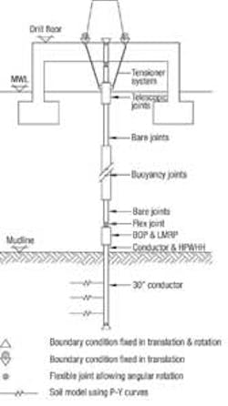
Two rig and riser systems are examined. In addition to the two riser systems, sensitivity analysis is performed over a range of water depths (100 m, 300 m, and 500 m). The riser stack-up for both systems is typical. The sixth generation stack-up includes a section of non-buoyant joints above the LFJ, which are included based on the prevailing philosophy for the system aimed at optimization of the recoil response of the riser.
The results are based on analysis using the non-linear FE software tool DeepRiser, which was developed to analyze top tension riser (TTR) drilling, completion, and workover risers. The formulation uses a 3D hybrid beam-column element with fully coupled axial, bending, and torsional degrees of freedom. It uses an iterative scheme to achieve a solution. The model includes a fully constrained boundary condition at the base of conductor. The riser is further constrained to the vessel at the drill floor both in translation and rotation. The tensioner sheaves or hang off shackles are constraint to the vessel in translation only. Soil with low un-drained shear strength is assumed for all cases, and the conductor system is modeled to a depth of 200 ft. below the mudline. Soil interaction with the conductor is modeled using a force deflection curve at each node along the conductor.
To simulate the environmental loads, dynamic wave simulations were performed. The analysis was performed in the time domain for sufficient duration so as to reach statistical convergence of the relevant load histories. Each fatigue calculation considers the full sea state scatter from a typical North Sea wave environment up to a cut off wave height of 8 m (26 ft). Each sea state from the wave scatter is simulated to capture the full range of response periods. A JONSWAP wave spectrum is used or all sea states. No current loading is included in the analysis, which is a conservative assumption as current loads can lead to hydrodynamic damping and hence lower cyclic loads. The first order vessel response to wave loading is model using vessel response amplitude operators (RAOs), which describe the vessel response in six degrees of freedom – heave, surge, sway, yaw, roll, and pitch.
Stress cycles at the relevant fatigue hotspots are calculated incorporating a stress concentration factor (SCF) which relates the nominal pipe stress to the localized peak stress in the component. This peak stress typically occurs in the root of a thread or at a weld due to misalignment between mating parts. Fatigue calculations use the rain flow counting method and the Palgren-Miner rule for fatigue damage accumulation.
Fatigue data
The fatigue calculations are made at fatigue hotspots on the 36-in. conductor. The fatigue critical hotspot in this conductor is the threaded connector that joins adjacent conductor sections. The S/N curve is referenced from DNV-RP-C203 for tubular joints with cathodic protection in seawater.
It is assumed that the conductor connector is always located at the point of maximum cyclic bending within the conductor system. This allows for ease of comparison among the various cases. However, in practice when designing the system, an effort is made to keep the conductor connectors in a region of lower cyclic bending moment to avoid excessive fatigue damage.
For ease of comparison fatigue life is present. Fatigue life in this case is defined as the length of time before excessive fatigue damage accumulates at the hotspot in question and leads to the hotspot reaching its fatigue limiting state.
Top tension setting
In modeling both third and sixth generation systems, a common method is used to calculate the top tension. Top tension is calculated in accordance with API RP 16Q to supply 200 kips over-pull at the base of the LMRP.
API RP 16Q Top Tension Recommendation states "A minimum tension setting is required to ensure the stability of the riser. The tension setting should be sufficiently high so that the effective tension is always positive in all parts of the riser even if a tensioner should fail." Hence the top tension setting,Tmin, is calculated according to the following equation.
| Tmin = TSRmin N/[Rf (N –n)] |
| Where: TSRmin = Minimum slip ring tension N = Number of tensioners Rf = Tension reduction factor resulting from fleet angle and mechanical efficiency n = Number of tensioners subject to sudden failure |
Wellhead fatigue comparison
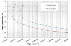
Fatigue calculations along the length of the wellhead and conductor system using the fatigue data set out in the preceding sections result from fatigue calculations based on the third generation and sixth generation drilling rigs in 300 m water depth.
Where no fatigue damage is found (i.e. infinite fatigue life) a life of 16 years is assumed for presentation purposes. This is evident below -50 ft. (15 m) where the fatigue life is constant at 16 years.
The minimum fatigue life occurs at 13 ft (4 m) below the mudline for both cases. The sixth generation rig and riser conduits impart higher levels of fatigue damage to the conductor system. The minimum fatigue life of the conductor is 0.04 years, or 14 days, for the sixth generation rig. The minimum fatigue life of the conductor on the third generation rig increases to 0.46 years or 168 days. The fatigue damage in the conductor for these conditions is 12 times larger when considering the sixth generation vessel. A similar, though smaller, trend is observed when comparing wellhead fatigue damage rate for varying rig type.
Water depth sensitivity
Fatigue calculations are performed for both the sixth and third generation systems for a water depth variation of ±200 m (656 ft.) from the base case (water depths of 100 m and 500 m). The aim is to quantify the relative change in fatigue damage in the conductor over a range of water depths.
The level of fatigue damage in the conductor decreases with increasing water depth. With increased water depth comes increased hydrodynamic damping as well as changes in to the mode response of the system. For example, the first mode response period increases from six seconds at 100 m to 25 seconds 500 m for the third generation system. This moves the primary natural response period away from the wave excitation periods and away from the natural response period of the BOP and conductor system. When comparing the third and sixth generation systems, the difference in fatigue life is a factor of 12 to 23 over the range of water depths considered. The trend for increased levels of fatigue damage in the wellhead and conductor system for the sixth generation rig is consistent over the range of water depths considered.
Tension sensitivity
The tensioning system supplies the tension to the riser string at the slip ring on the outer barrel of the telescopic joint. The tensioning philosophy used is from API RP 16Q and considers a 200 kips over-pull at the base of the LMRP. The same philosophy is used for both the third and sixth generation rigs. Sensitivity analysis considers reduced levels of riser tension with the aim of applying 100 kips and 50 kips over-pull at the LMRP. The goal is to measure the effects that reduced levels of over-pull have on conductor fatigue. The sensitivity is based on a 300 m water depth. The fatigue life of the conductor increases from 168 days to 392 days when considering the reduced levels of over-pull for the third generation system. Conversely, the sixth generation system is less sensitive to the tension setting, with a slight reduction in fatigue life for the reduced levels of over-pull. This suggests that for the conditions considered a lower over-pull setting is more appropriate for third generation systems while higher level of over-pull is desirable for sixth generation systems. A notable observation from this sensitivity is that regardless of the tension setting the minimum fatigue life is consistently lower for the sixth generation systems.
Parametric study
A consistent trend of increased conductor fatigue damage is seen when comparing the sixth generation system with the third generation system. The increased level of fatigue damage shown for shallow to moderate water depths over a variety of top tension settings help to understand the system parameters that drive this difference. The parametric study considers the following system variables:
- BOP
- Riser joints
- Flex joint stiffness
- Vessel response.
The parametric study uses the sixth generation rig and riser model as a base case. System parameters from the sixth generation rig model are then replaced with third generation system data and fatigue is calculated.
The first sensitivity considers the model of the sixth generation system with the BOP replaced with third generation BOP properties. The aim is to quantify the influence of the BOP stack on the predicted levels of fatigue damage in the conductor. By replacing the model of the BOP in this way, the weight of the structure is reduced from 730 kips to 450 kips, and the overall elevation of the stack from the wellhead to the top of the LMRP is reduced by 13 ft. The effect of replacing the sixth generation BOP with the third generation BOP is significant, with the minimum predicted fatigue life increasing from 14 days to 236 days, or a factor of 17.
This increase in fatigue life may be partly attributed to two factors. First, the primary natural response period of the BOP stack and wellhead conductor system reduces slightly and shifts away from the wave excitation periods. Second, the reduced weight and length of the BOP stack reduces the lever arm effect of the BOP stack on the wellhead as a result of riser motion at the LFJ. This motion results from displacements of the vessel and riser system which propagate down the riser to the LFJ. At this point the bending moment in the riser system is alleviated by rotational deflection of the LFJ. However, motions in the translation DOFs are not reduced and are transferred into the BOP stack.
Influence of the riser joints on the predicted fatigue damage in the conductor is also investigated. For this sensitivity the sixth generation riser joint properties and running order is replaced with the third generation riser joints and running order. The aim is to quantify the influence that the riser joints and joint running order have on the predicted levels of fatigue damage in the conductor.
There are noticeable differences when com- paring the sixth generation riser joint to the third generation joints. First, the wall thickness of the joints is reduced from ¾ in. to ½ in., which has the effect of reducing the mass and stiffness of the joints. Second, the hydrodynamic diameter of the buoyant sections is reduced from 55 in. to 40 in., which reduces hydrodynamic loading.
The effect of replacing the sixth generation riser joints with the third generation riser joints shows a significant reduction in fatigue life from 14 days to six days. Considering the relative change, this represents a reduced fatigue life of over 100% compared to the base case. Reasons for the reduced fatigue life when considering the third generation riser joints is due partly to joint properties and partly to the difference in running order. The reduced hydrodynamic diameter of the third generation joints reduces the level of hydrodynamic damping (energy loss from the system) along the length of the system which may drive larger riser motion in the lower water column.
To investigate the influence of the flex joints on fatigue damage in the conductor, the sixth generation flex joint rotational stiffness is replaced with the third generation flex joint stiffness factor. The aim of this sensitivity is to measure the influence that the flex joints have on the predicted levels of fatigue damage in the conductor. There are noticeable differences in rotational stiffness when comparing the flex joints from the sixth generation and third generation rig. The flex joint on the sixth generation rig has a higher rotational stiffness with the LFJ stiffness increasing from 20 ft.kips/deg to 68 ft.kips/deg when compared to the third generation system. The effect of replacing the sixth generation flex joints with the third generation flex joints shows only a marginal increase in fatigue life from 14 days to 15 days.
The influence of vessel response to first order wave loading of the fatigue damage in the conductor is investigated. For this, the sixth generation vessel motion RAOs are replaced with the third generation vessel motion RAOs. The aim is to quantify the influence of the different vessel motion characteristics on the predicted levels of fatigue damage in the conductor. The effect of replacing the sixth generation vessel motion RAOs with the third generation RAOs shows only a marginal increase in fatigue life from 14 days to 16 days.


