Douglas Farley
Ivan A. Barannikow
Brandon L. Bourg
Weatherford
Demanding deepwater drilling environments require cementing technologies that are engineered to deliver high reliability and increase well life. Yet because of its early adoption by the industry, float equipment is often considered a low-tech commodity product. As such, operators might be tempted to select float equipment based on cost alone, with little regard to how its design influences the cementing job.
Float equipment design and selection involves nuances that may not be readily apparent. This seemingly simple cementing product must withstand extreme conditions of backpressure, plug bump pressure, tensile force, and flow-induced abrasion. Without fully understanding these nuances, the operator runs the risk of selecting a float equipment package that is less than ideal for a given cementing application.
Design-related failures
Inadequacies in design leave float equipment vulnerable to failure. For example, the valve design must provide sufficient flow area and minimal restrictions for the passage of debris. In some instances, objects dropped or pumped into the casing cannot easily pass through the valve, thus blocking the flow path and leading to a failure.
Debris can also settle in the mud system and accumulate between the plug and the float equipment. When running in autofill mode, the tight annular clearance forces fluid into the float equipment and liner running tools. Running a filter shoe below the shoe track may capture debris and minimize plugging risks. However, any flow restriction in the float equipment raises the risk of poor cement placement, reduced well integrity, and significant nonproductive time related to remedial interventions and additional drill-outs.
Industry guidelines
Operators may use the recommended practices set forth in API RP10F, “Recommended Practice for Performance Testing of Cementing Float Equipment,” as a guide for selecting float equipment. However, RP10F is only applicable for float equipment that contacts water-based fluids used for drilling and cementing wells, not for float equipment in non-water-based fluids. Moreover, it is merely a recommendation and not a recognized standard specification.
API Specification 10F, which is still under review at the time of writing this article, addresses these shortcomings. The specification more accurately describes the performance of each piece of float equipment and separate testing parameters for each component. The specification’s testing parameters also expand the forward and reverse flow duration, the forward flow rates, and the maximum pressures currently dictated in API RP10F.
While API 10F will help users better understand the performance of the float equipment and make the best selection for different applications, it still falls short in addressing drillability and plug bump ratings. A deeper understanding of all the parameters that inform float equipment design is required if operators are to identify and select the most appropriate and cost-effective equipment for each well.
Float equipment architecture
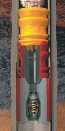
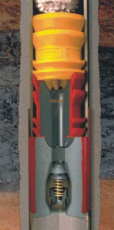
At first glance, the three main components comprising float equipment - the steel hull, the valve, and the concrete - all look fairly simple and straightforward. Upon closer review, however, one realizes that each component is critically important and must interact effectively to hold differential pressure from above and below.
The steel hull acts as an outer shell, designed and manufactured to meet the customer’s connection, material, and rating requirements for burst pressure, collapse pressure, and tensile strength. This outer shell’s wicker pattern profile on its inside diameter is vital for securing the valve inside the float equipment.
The choice of valve configuration in most float equipment commonly comes down to two options. Many manufacturers employ a poppet valve, which features a spring-loaded poppet that seals against a seat. Flapper valves provide a larger flow area and less tortuous flow path compared to poppet valves, thus making the flapper design better equipped to handle higher flow rates and more tolerant to lost circulation materials. Poppet valves exhibit greater reliability in many applications, with higher backpressure ratings in a more cost-effective body design.
The quality of concrete used to secure the valve to the outer shell is of paramount importance. The shrinkage and shear bond of the concrete determine the sealing ability between the shell and the valve and prevent the cured concrete from spinning inside the shell during drillout. The concrete’s compressive strength and flexural strength are directly related to its ability to support plug bump pressures and retain backpressure. While concrete quality and consistency are determined by various ASTM standards, quality control measures such as sieve analysis and compression tests are also crucial to ensuring product consistency and a reliable sealing surface.
Deepwater operators are increasingly adopting autofill float equipment for their wells. This equipment allows the casing to self-fill while running downhole, thus reducing both surge pressure and the equivalent circulating density that could fracture weak formations. Autofill float equipment also increases tripping speed by eliminating the trip time needed to fill up the casing. The complexity of deactivating the autofill feature can lead to equipment failure and significant rig-time loss. To mitigate these risks, autofill operations must maintain seamless communication between float equipment support functions, drilling engineers, and the rig crew about what action is required to deactivate autofill float equipment.
While the individual design parameters of each component are important, the components must also work seamlessly together to achieve operational success. The ability to withstand backpressure or the ability to keep the hydrostatic head of the cement column contained in the annulus is determined by the component strength of the valve, the flexural and shear strength of the concrete, and the groove type and pattern of the shell. The physical properties of the concrete and the groove pattern also determine the pressure rating of the plug bump. In addition, the float equipment valve must resist erosion from prolonged circulation of sand-laden drilling muds in both forward and reverse flow. These attributes must remain consistent and reliable at temperatures up to 400°F.
Pre-job planning
Failure modes are typically attributed to design flaws or manufacturing errors - but sometimes a perceived float equipment failure is simply the result of underestimating fluid compression. This is particularly true in deepwater wells drilled to greater reservoir depths, which may require displacement volumes of more than 2,000 bbl behind the top dart/plug. The use of highly compressible synthetic-based muds can result in high amounts of compression even with low bump pressures. Bleedback volumes of more than 20 bbl are not unusual.
Overcoming this problem requires a compressibility calculator that accounts for the inherent compression caused by hydrostatic pressure of the fluid in vertical wells and that accounts for variations in fluid compressibility between water and synthetic-based muds. Procedures are also required for handling bleedback volumes, knowing when floats are holding and allowing excess fluid to bleed back, and knowing when floats are not holding and then applying pressure until cement is available.
Conclusion
The transition from API RP10F to the specification API 10F will better inform the end user, more accurately describe the specific performance of each piece of float equipment, and result in industry-standard equipment. However, the specification should not be the sole reference point in the purchasing decision. A detailed understanding of performance properties and accurate compressibility calculations can mean the difference between allowing sufficient flowback and experiencing a float failure that damages the integrity of the well beyond repair.


