Monitoring position of formation and fluid boundaries
Egbert Waterman, Petrotrin Trinmar Operations,
John Alvarado, Schlumberger
As demand for oil soars, operators look for ways to enhance the production capabilities of existing assets. Enhanced production was the impetus for Petrotrin, the national oil company of Trinidad and Tobago, to drill a horizontal well in a thin, near-shore sand deposit.
Previous attempts at horizontal wells through this tricky, thin sand were disappointing because of the difficulty in maintaining the wellpath. As a result of a new geo-steering technology designed to improve exposure to the hydrocarbon interval, Petrotrin was able to exceed its goal of a 400-ft lateral section to successfully penetrate more than 1,325 ft of oil-bearing sand.
In 2003, Petrotrin Trinmar Operations (Trinm- ar) and Schlumberger initiated a study on the North Soldado field, off the southwest coast of Trinidad, which identified six new drilling locations and two sidetracks as candidates for production improvement. Two of these candidates, P524 and P363, were to be horizontally placed in the Marker-40 (M-40) sand, a thin near-shore sand deposit overlying the Manzanilla unconformity. The thin, undulating M-40 sand is a very difficult section in which to drill a horizontal well with a high net-to-gross ratio.
In August 2005, Trinmar’s drilling operations began on the S854 (candidate P524) well, which had three sections: 16-in., 12 1/4-in. and an 8 1/2-in. lateral section. Total depth (TD) of the well was 6,580 ft with the lateral kicking off at MD 5,071 ft.
Two of the main company well objectives were to attempt to land the S854 lateral section without a pilot hole and drill the 8-1/2-in. section without exiting the M-40 sand.
Contributing significantly to the operator’s decision to move forward with this project was the decision to use, in the 8 1/2-in. lateral section of the well, a new geo-steering technology designed to improve the exposure to hydrocarbon intervals. Schlumberger’s technology is the industry’s first and only deep directional drilling induction LWD tool, making it possible to continuously monitor the position of formation and fluid boundaries up to 15 ft away. This 15-ft monitoring facilitates proactive geo-steering decisions in “real” time. The operator was one of the first companies to use this technology in this area of the world.
The drilling team was composed of members from both the operator and the service company. Extensive pre-drilling planning was conducted to establish and clarify roles, responsibilities, logistics and communications.
Drilling lateral section
The team ran LWD measurements in the 8 1⁄2-in. lateral section of the well that included:
• Array Compensated Resistivity (ARC-6): (Induction) GR-Res, APWD.
• GeoVISION Resistivity (GVR-6): (Lateralog) Azimuthal GR, Bit Resistivity, Ring Resistivity, Images.
• PeriScope 15: Deep reading distance and direction to boundaries.
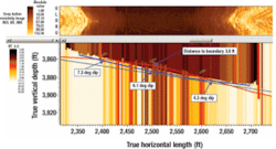
The team kicked off the lateral out of the casing shoe at MD 5,071 ft, at which point the tool indicated a shale boundary 3 ft above the wellbore. Between 5,113 ft and 5,209 ft, the team’s bottom hole assembly (BHA) was moving away from the upper boundary and began tracking the lower boundary; at this point steering began to direct the BHA into the upper portion of the sand. At 5,330 ft the BHA began to move away from the lower boundary, up through the sand. The team built a rate of 89.2° (instead of the 87° anticipated) due to the formation, with the shale dipping towards the wellbore. At this point, the rig was instructed to steer down to avoid entering the shale.
At 5,435 ft, the team’s BHA exited the roof of the sand while steering down to avoid the aggressively down dipping formation. The drop rates being obtained were not enough to overcome the sharp change in dip. At this point drilling was stopped and a team assessment was made on the best plan forward to minimize the loss of section within the acceptable completion doglegs for the wellbore.
At 5,614 ft, the team’s BHA re-entered the sand at approximately 80° and instructed the rig to steer up to 84° to avoid drilling down through the sand. At 5,799 ft, the team instructed the rig to build to 85°. At 5,850 ft, the team indicated the roof of the shale boundary was rapidly approaching the wellbore, but the bit was still in the sand. The team continued drilling through a possible pinch out maintaining the angle. At this point, the well was drilling through a minimum sand thickness of 3 ft and continued as follows:
• By 5,880 ft, the roof of the shale boundary was rapidly moving away from the wellbore and the bit was still in the sand. It is possible there was thickening of the sand at this point. The team instructed the rig to maintain 85°.
• At 5,890 ft, the upper shale boundary was undulating 5 to 8 ft above the wellbore. The team instructed the rig to maintain 85.5°. At 6,338 ft, the bit resistivity dropped to 30 ohm, indicating the upper boundary was approaching the wellbore and the rig was instructed to drop to 84°.
•At 6,515 ft, the upper boundary was rapidly approaching the wellbore as expected. The team’s decision was made not to steer down and continue following the sand as the dogleg would be outside the completion parameters and the decision was made to TD the well at 6,580 ft.
Using the tool, the team’s decision to break the build tendency began at approximately 5,350 ft, which was 85 ft before entering the shale at 5,435 ft. At this point, the top of the sand was 7 1⁄2 ft above the well trajectory. The team applied an increased drop setting to the rotary steerable, but because of the drop rates being obtained in this formation and the rapid change in the formation dip, the shale could not be avoided without putting a high dogleg into the wellbore.
On entering the shale, the tool continued to map the top of the sand, and based on dips calculated, a revision of a maximum dogleg was requested and obtained. The team continued to drill with the rotary steerable system to give maximum drop. As a comparison, if geosteering had been performed with a conventional assembly, it would not have been possible to react to the formation dip change until the sensor was at or very close to the boundary. As such, it would have taken a significantly longer section to re-enter the sand, if the direction to steer was known.
The team had planned to drill the well without a pilot hole. The decision to attempt this was based on an original plan to land S854 close to offset well P524, to reduce the uncertainty of the M-40 sand location. However, this advantage was negated when the landing was changed (the heel was moved backwards and there was a change in the well azimuth) to allow for a longer lateral. The new landing location would have used sand depth maps and seismic for well planning, fielding much greater uncertainty in the M-40 sand location.
Future wells
The team can land future wells without a pilot hole if the landing location is close to a logged offset well. However, team contingency plans should always be in place to make the landing into a pilot hole due to the uncertain nature of these complex formations.
This technology played a significant role in the ability to drill such a long lateral section through such a complex formation, better able to navigate the severe dipping and faulting, making it possible to economically drill this well. The trajectory stayed a few feet from the top of the sand, even as sand thickness varied from above 10 ft to as low as only 3 ft thick. This allowed the drilling assembly to stay within the sand with only a single exit, a result of an inability to rapidly change the wellpath within a particularly severe dip change. Even in this case, the amount of lateral section lost was minimized as a responsive steering decision was made before actually exiting the sand, which would not have been possible with conventional geo-steering.
A total of 1,325 ft of net pay sand was obtained at an 88% net-to-gross ratio. With more experience, the net pay is expected to improve for future wells.•
